

 Thanks:
  Likes:
  Needs Pictures:
  Picture(s) thanks:
Results 61 to 75 of 101
-
11th February 2016, 04:09 PM #61
 .
.


- Join Date
- Feb 2006
- Location
- Perth
- Posts
- 27,790
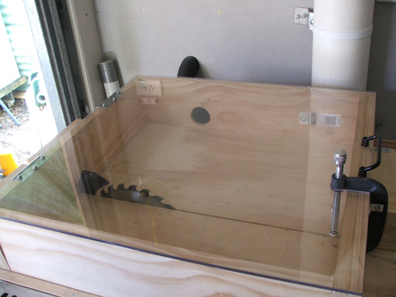
 The principle of using a box like this has a number of problems which is why it is not used
 Originally Posted by MandJ

If this box does not have a vent allowing air in, the shop vac will suck very little air and fine dust out of it.
The other thing is the position of the outlet.
A cross flow (across the blade will not be anywhere near as effective as a flow that utilises the natural flow of the air coming off the blade
The best place for the outlet is immediately in front of the blade so just below your handle and the inlet should be immediately behind the blade.
The next thing is the size of the box relative to the flow of a shop vac.
The box looks like it is about 1 ft x 3 x 3 or about 9 cubic ft.
A working shop vac will generate about 70 CFM under optimum conditions and about half that under constrictive conditions.
This means in theory the box volume will take about 9/25x 60 = ~15 seconds to clear.
However in practice due to turbulence it clears bout equal amounts of fresh air as it does dust so it takes about 15 seconds to clear about half the dust in the air and another 15 seconds to clear the remaining 1/4. and 15 seconds to clear the next 1/8 etc.
So what this means in practice is that once you make a cut (i.e. very quick and because of blade turbulence the box instantly fills with a high concentration of fine dust - way before it can be captured) you have to wait for 15 seconds for the shop vac to clear half the dust and another 15 seconds to clear 1/2 the remaining dust etc.
To vent 99% of the dust you need ~7 x 15 = 105s !!!!
If you open the box before that you will spill fine dust into the workshop.
Now contrast that with a DC and a 4" duct in practice carrying about 200 CFM through such a turbulent set up..
9/200 x60 = 2.7 s , so much better than the shop vac but if you want to clear 99% of the dust you will need to wait for 7 x 2.7 s = 20s
Now we both know that waiting for 20 seconds before opening the box is just not going to happen
It much better to grab as much of the dust immediately at the source and then use the DC to vent any of the fine dust that spilled into the workshop.
BTW if you keep using the box, to assist the flow I would suggest a number (2 on each side) of air inlet vents but unless you vent it with the DC the dust may leak out through the holes.
-
11th February 2016 04:09 PM # ADSGoogle Adsense Advertisement
- Join Date
- Always
- Location
- Advertising world
- Posts
- Many
-
11th February 2016, 04:34 PM #62
Supporting my wife's hobby.
- Join Date
- Nov 2013
- Location
- Caboolture QLD AU
- Posts
- 781
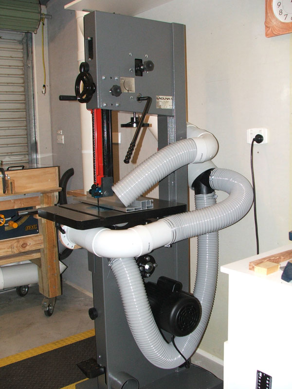
Hi Bob, what you can't see is a 7" x 2" cutout on the lower LH side, it's interesting that the air flowing into that opening pulled a shop rag from outside the box and almost into the VAC, snagged on the saw blade - wasn't running.
I thought about the dust inside, I do wait around 5 seconds before opening it. Keep in mind that I have a cyclone of air coming from behind me (rear lower well mounted blower), when I open the lid.
On the stuff I have cut so far, there has been nothing inside, however that will likely change when I cut thicker and bigger material. Realising that I still need to open up the lower cabinet, I've been thinking instead of taking a 100mm flex from the 150mm hardline running to the cabinet port below the table and bring that up to the side, I can then completely open up the lower LH side of the slide to match the increase flow.
You can see why I love that air flow from the rear of the work shed - I am highly allergic to pine dust, even using a hand saw outside will get me started with sinus, I've cut over a dozen pieces of pine with the slide and not even a sniffle.
EDIT:
Size is 5" x 22" x 23" which is about 1 and 1/2 a cubic foot. Looks like the shop vac might do that? - a 100mm port with corresponding intake should easily do it?
I thoughtabout having the pickup where you suggested, but being a slide, that point canbe almost two feet away from the frontof the blade, it is continually shifting with the slide.
-
11th February 2016, 06:16 PM #63
.
- Join Date
- Feb 2006
- Location
- Perth
- Posts
- 27,790
5 x22 x23" is 1.46 cuft, is that the internal size of the box? - it looks a lot deeper than 5" to me Originally Posted by MandJ
1.46/35 x 60 x7 = 17 second wait for 99% air removal with a VC
1.46/200 x60 x7 = 3 seconds with the 100 mm on the DC.
I still reckon a series of holes at least along one side would be better than a single 1 , 7 x 2" opening. what happens is a cylinder between the inlet and outlet are cleared of dust but the rest of the dust stays in the box and is only slowly scavenged out of the box.
-
11th February 2016, 07:57 PM #64
Supporting my wife's hobby.
- Join Date
- Nov 2013
- Location
- Caboolture QLD AU
- Posts
- 781
Didn't realise I'd left out the one in front of the 1/2. This online edit window is dropping 3 or so key press, or just hangs on me.
I am going to modify it for 100mm anyway, it means that I only have one DC hose connection to the table, so that slot will be almost the length of one side. I wanted a slot so that I could occasionally fit a 6" x 3ft plank into the slide. The other alternative would be to leave the 7" slot and drill a series of holes.
BTW the modified G-clamp at the front in the picture is a 5" clamp.
-
11th February 2016, 08:16 PM #65
.
- Join Date
- Feb 2006
- Location
- Perth
- Posts
- 27,790
Good idea. Originally Posted by MandJ
makes senseI wanted a slot so that I could occasionally fit a 6" x 3ft plank into the slide..
OKBTW the modified G-clamp at the front in the picture is a 5" clamp.
-
14th February 2016, 10:51 AM #66
Supporting my wife's hobby.
- Join Date
- Nov 2013
- Location
- Caboolture QLD AU
- Posts
- 781
Spent the day cutting 1m lengths of timber into 1/4" strips and testing various ways to get the best dust extraction from below the band saw table. Using a tissue to wipe of everything after each modification and help with identifying the best pickup method with this BS.
I tried a bare 100mm flex up close and at various distances / positions, I tried a small part bell mouth but it still felt like the air would rather pull around the intake mouth rather than across the blade and guides, there is plenty of space around them but it's a wider and narrower path, obviously more resistance to flow.
-
14th February 2016, 10:55 AM #67
Supporting my wife's hobby.
- Join Date
- Nov 2013
- Location
- Caboolture QLD AU
- Posts
- 781
DC Problems:
1: A blade guard is attached to the lower cabinet door, it has two locking knobs and has to be slid down before the door can be opened, otherwise it hits on the LH table lock lever, and it's a right angled plate that also covers the side of the blade and the front part of the blade guides, this tends to make dust/chip extraction difficult.
2: The DC pickup needs to be easily moved out of the way when I want to adjust the lower guides.
3: Table tilts, so the pickup needs to be moved to accommodate.
Guard lowered.
My final solution involved a few compromises, but 99% of the time we will be using the BS it's actually easier to use now and the side blade guide in no longer used.
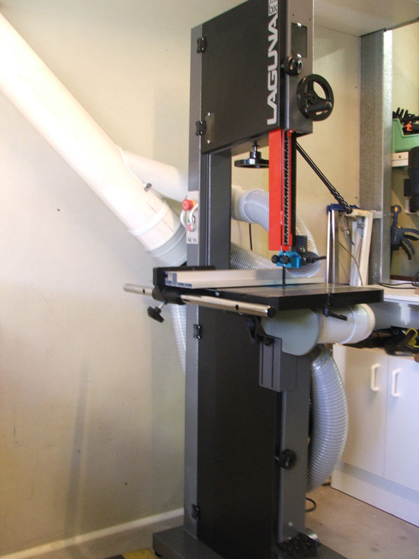
There is a large unused threaded hole through the cast iron Trunion plate on the RH side, I mounted a right angle bracket there and bolted a Flex to PVC adaptor to it, it connects into a 90 PVC bend that comes around the front of the BS below that table, a piece of 100mm pipe with part of the side cutout is fitted into the other end of the 90 bend. This complete assembly is rigid and friction mounted at the angle bracket, it is simply pushed down about 6" to give complete unhindered access to the lower guides for adjustment, you just lift it back up for dust pickup.
I made a blade guard end cap for the pipe pickup, it simply pulls off or pushes on when access is needed, unlike the original guard, it does not need to be removed to open the lower door. It exposes the entire lower guide and blade to the DC pickup, the air is now drawn across the lower guides and blade, for the first time there is air being pulled down through the table insert.
I cut the equivalent of 6 meters of timber, and at last there was no dust buildup below the table or up around the top of the lower guides.
-
14th February 2016, 12:18 PM #68
Supporting my wife's hobby.
- Join Date
- Nov 2013
- Location
- Caboolture QLD AU
- Posts
- 781
I still have not got the - above table - pickup sorted, but FYI this is the table after a 3m cut through pine. This of course proves nothing as far as table top pickup goes, I'm sure it will go pear shaped when large Resawing is carried out, but this was always going to be a trial / error learning experience.
But after viewing various youtube videos of people using the 14-12 with totally useless pickup - like 2 x 4" connections to a single 4" flex pipe going back to the main - and then seeing a pile of saw dust over the table, the floor and the flex leading to the ports, after one short resaw, they open the lower door and show what I would describe as "sawdust everywhere", then usually say something like "the BS DC setup works well" ?
I'm pretty happy so far and as always, l have a ton of airflow past me and the equipment via a 700mm fan intake in the lower rear wall, this air exits 2m behind me and up near the ceiling, and also via a soon to be added fan extractor in the high part of the roof, which will auto run a few hours after the DC is shutdown.
-
15th February 2016, 11:13 AM #69
Member
- Join Date
- Jul 2015
- Location
- New Zealand
- Posts
- 69
MandJ - thanks for all your posts on this. I've been reading and enjoying/learning from what you've done. I'm in the process of planning out a long term dust extraction solution and hope to do something similar to what you've done. I have a very similar 3hp dusty to yours which I intend to mount outside in a similar fashion.
The next question on my mind is how to go about opening up the tool ports. I like what you've done with the bandsaw. You've also given a few glimpses of your table saw - any chance you could put up a few more pics of what else you've done there? I'm intending on building my table saw into a movable cabinet and hooking up a 125mm at the bottom and 100mm overhead, but I'm keen to hear more about how successful you have been (or not if that's the case).
The latest question I've been pondering on the table saw is how to let enough air into the cabinet to make the 125mm port at the bottom worthwhile. I've got one of those Carbatec contractors saws (i.e. with the motor hanging out the back) and I'm intending to enclose the motor and just leave a few air vents (strips) to at the back to keep some air flowing around the motor. Then the plan is to seal up the gap at the top between the cabinet and the table probably with some expanding foam. And I've got some magnetic sheet to put around the crank handle at the front to close up the large gap there. But my concern is that if I do all of this then will I have choked off the 125mm lower port too much? And if so, where should I be leaving the gaps?
-
15th February 2016, 12:19 PM #70
.
- Join Date
- Feb 2006
- Location
- Perth
- Posts
- 27,790
Mandy your BS DC implementation is turning into one of the best I have seen. Well done!
How easy is it to disconnect the ducting under the table?
I change my blades quite often (sometimes 2/3 times a day) and that is why I have not made anything fixed underneath and is mainly why I just jam a length of flexy under the table, but dust wise it looks like it's not as effective as your setup.
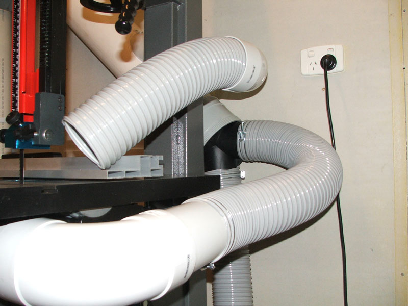
For anyone else considering BD extraction a couple of minor points that will help improve things even more.
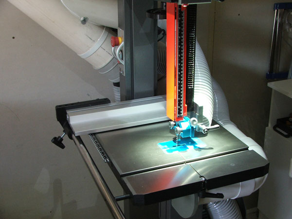
BSsetup.jpg
The ducting junction at A will be considerably more restrictive than a 150-100 mm Y junction. The main reason for this is that the black Y in the photo has the two incoming air streams strike each other at 90� and so they slow each other down and generate turbulence. I do appreciate that a 150-100 mm Y junction takes up more room and costs a lot more. In M&Js setup the amount of air coming into B & C under the saw table is reduced because of the choking effect of the machine connections so the effect will not be as bad.
On my BS when cutting anything more than about 25 mm thick I get a lot of sawdust in between the wood and the outfeed side of the table and it eventually spills off the end of the outfeed side of the table in the region marked with the red line blob in the above picture. I have been thinking that it might be worth actually making add of line B a 150 mm connect and cutting holes/gaps in the region of the red blob.
There is no need to worry about cooling the motor as it should look after itself. Originally Posted by WoodyNZ
The best place to put the major extraction point is to make a plastic or Al hopper with its lowest point directly underneath the blade or towards the front and locate the extraction point in the hopper such that the blade shoots the sawdust straight into the extraction point.
I do not recommend closing up any of the existing gaps between the table and the cabinet, or around any of the handles as these gaps are small and you need as much air flow as possible coming into the cabinet at the front of the saw. I would even suggest making more holes in the front of the cabinet. Closing up the gap at the back near the motor is a good idea provided there are enough gaps left near the front.
-
15th February 2016, 01:54 PM #71
Supporting my wife's hobby.
- Join Date
- Nov 2013
- Location
- Caboolture QLD AU
- Posts
- 781
BobL, I was wondering when you'd mention the black Y fitting, something I bought for $10 (cutout the plastic grate inside) and am using until I could see if I could make my own 100mm takeoff from the 150mm line. It was actually relatively easy and I could see the difference in static pressure and current between the two fittings, the one I made is so much better, and that is my next task, to junk that black crap and graft another 2 100mm low angle ports into the 150mm.
That under table pipe is really easy remove if needed, it's held on by one big bolt, I've slotted the fitting so that the bolt can be loosened and pipe slid out.
However in my case, when you pop off the end-cap / blade guard, the open end of the 100mm pipe finishes 1/16" before the table blade removal slot, so in my case I don't have to remove it.
The mounting bolt and a few big washers gives me a really good friction point that allows me to pivot the pipe down 6" at the front , I then have complete unhindered access to the lower guide adjusters, when finished, I lift it back up, put the end cap on and I'm done.
Love your idea of a bit of a catcher and fitting into the pipe running along the end of the table, I was surprised how much builds up in a high cut and flows off the table at that end, that will be simple to add.
WoodyNZ: Thanks for the encouragement, I have not closed off any gaps, holes, or slots in the cabinet, instead I added lot's more, I have 2 x 100mm holes on the LH side of the cabinet and another on the RH side, there is also a 100mm square vent onthe RH side that I may open up. I have a 150mm extraction point straight out of the bottom of the cabinet, I made sloping sides that lead down into that 150mm port and placed a few small corner vents for airflow into the cabinet to purge the corners, where there would likely have been little air flow.
The motor is inside and the airflow into / through the cabinet is impressive, so there is no danger of overheating the motor. I purposely placed the extraction port and one of the intake ports so that a lot of air flow was across and down away from the motor and belt, I was also trying to keep the sawdust from holding in the pulley, which is partly what the original plastic guard (piece of crap) was doing. It seems to have been a success as everything is still clean below that table.
-
15th February 2016, 04:45 PM #72
Supporting my wife's hobby.
- Join Date
- Nov 2013
- Location
- Caboolture QLD AU
- Posts
- 781
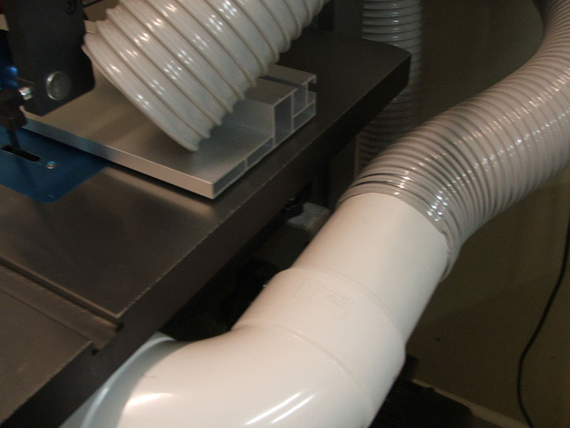
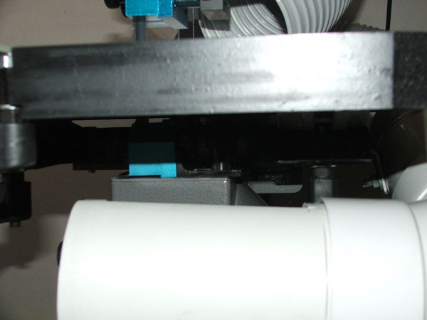
Not the best picture but this is with the End-cap / Blade guard removed and the pickup lowered, everything looks small in the picture.
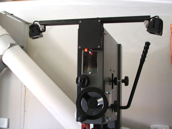
Just finished a work light for the BS, there is an optional 40W Halogen unit for this BS, but it costs around $170.00, I watched a few videos of it in use and was not that impressed with the brightness or the coverage.
I found a bundled pair of LED spots lights for around $74 from Jaycar - a bit expensive but they are brilliant (pun intended). Each light is rated at 10W and 720 Lumens (equivalent to a around 55W globe), they run from 9-60 VDC. Made of cast alloy, they are relatively small @ 51mm x 51mm x 61mm(D) and are a very attractive quality looking light,I powered them from an old Laptop supply I had lying around (15V @ 3A). They come with nice mounting hardware and can be set to any directional position.
I wanted something that would not get in the way, something I didn't have to adjust or move. I mounted a bit of aluminum tube to the top of a spare die-cast box that I had lying around, fitted a switch to select one, both or all lights off. They light both sides of the blade, and I have not bumped them once.
The fixture mounts using the existing holes on the face of the BS, I have also fitted a big RED Warning LED to the bottom of the mounting box. As the lights are powered from the BS inbuilt 240V socket, whenever the BS is plugged in and the wall socket is on , the LED glows a very bright visible warning indicator that the BS is powered. Obviously if the work lights are on then it's even harder not to notice there is power to the BS.
The camera flash makes the BIG red LED (1/2" diameter) appear dimmer that it really is.
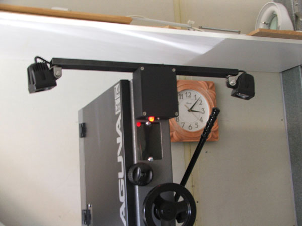
Brightness of the Lights makes the auto-iris close, so picture looks dim.
BTW I like the safety lockout on this BS, it can be pushed to stop the BS (there is separate off SW as well) or pushed any time you want extra safety. After being pushed, there is no way to start the BS with the On switch without first twisting the red outer casing on the lockout SW and pulling it fully out. Also love the way you can press the foot brake and almost instantly stop the blade - that real Disk brake really works and it takes very little pressure.
-
16th February 2016, 05:20 PM #73
Supporting my wife's hobby.
- Join Date
- Nov 2013
- Location
- Caboolture QLD AU
- Posts
- 781
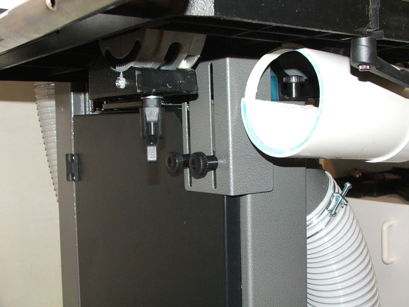
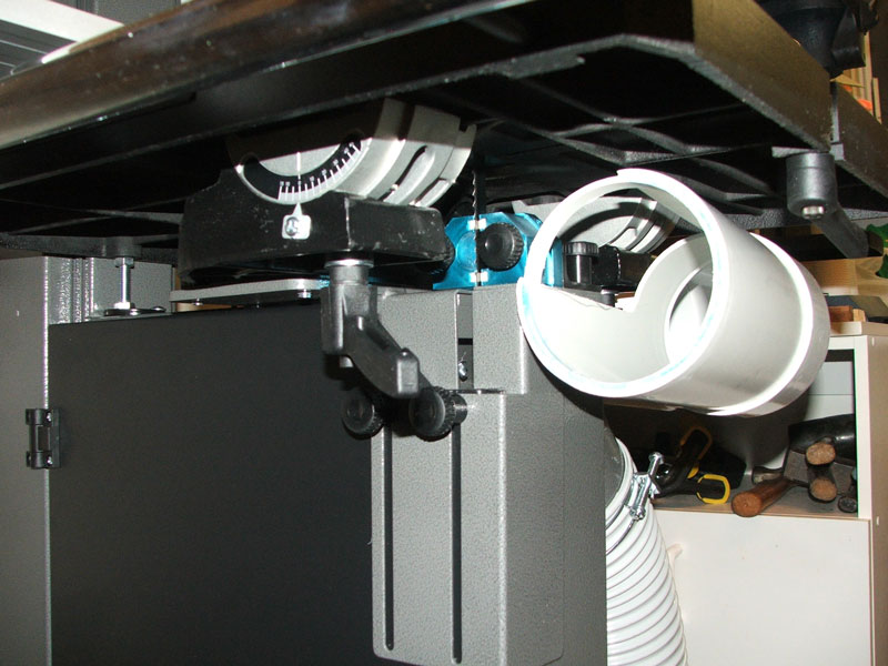
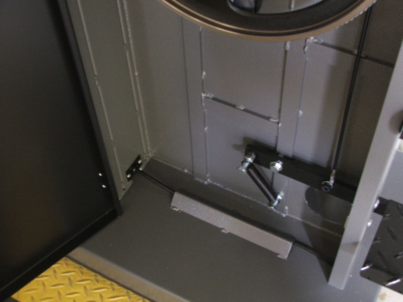
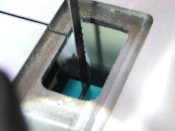
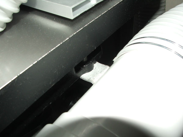
After having so much success with the below table dust hood, I decided to look even closer at the air paths and alignment of the pickup with respect to the blade gullet and guides.
I removed the blade and the table insert and found that I really needed to move the dust hood end-cap / blades guard that I made, about 1" to the right, this would allow even more air intake past the blade teeth, however if I did that, then it made the removal of the end-cap difficult and the longer pickup hood would cover the blade removal slot - something BobL was talking about previously.
Tests with paper ribbon showed a lot of air coming from 2" gaps below each end of the pickup hood slot, there is plenty of room for the air to travel past both ends of the guides and blade, but these gaps were closer to the intake, so I found a way to quickly fix that and at the same time, what I wanted was to have the air intake path flow between the two table mount Trunions, I have succeeded in doing that, that area is very wide and should not restrict air intake.
I also found that I could permanently fix the end-cap / blade guard to the hood, with an even simpler way to remove the pickup hood with end-cap attached, and also it solves every problem there could possibly be with below table access, blade changing and adjustment.
As the flex to 100mm pipe adaptor is bolted to the table, it makes it very "very" easy to simply pull the right angle connector and dust hood straight back from below the table. No more lowering needed, and it's just as easy to put back, seriously - it takes 1 second to remove and all of two seconds to put back on.
After making the new pickup, I retested air flow with ribbons and also checked static pressure and DC current with and without the new pickup hood. The results are very good, the complete hood with right angle fitting changes the current and static pressure exactly the same amount as 400mm of flex, I know it's not really scientific, but the ribbons show a substantial increase in activity and flow across the guides and blade, and now all of it coming from the other side of the guides and blade and flowing very strongly into the intake.
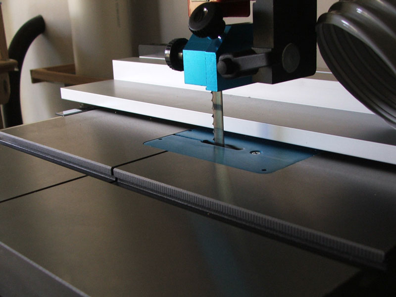
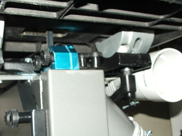
Tried to take picture but everything look cramped due to field of view, it's really open in there,the white is the back wall of the 100mm pickup and is 150mm from the blade.
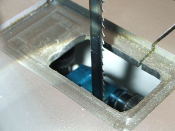
Same again, looks cramped but it's not, the green colour at the top part of the pic is my end-cap / blade guard and is 50mm from the blade teeth.
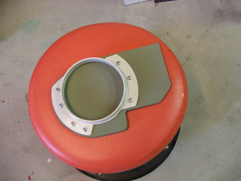
New longer dust pickup hood.
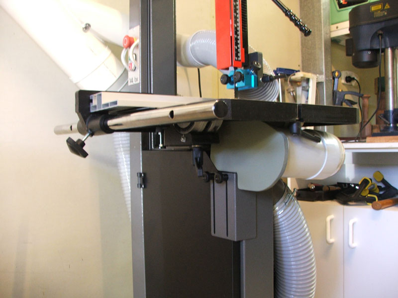
Complete hood removes from the side of the table pipe join.
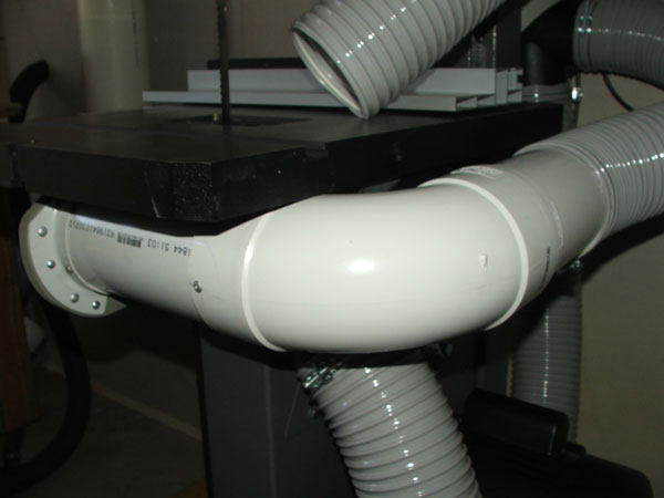
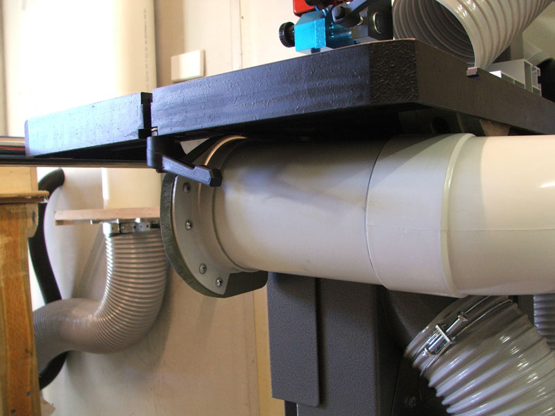
Dust pickup Hood removed.
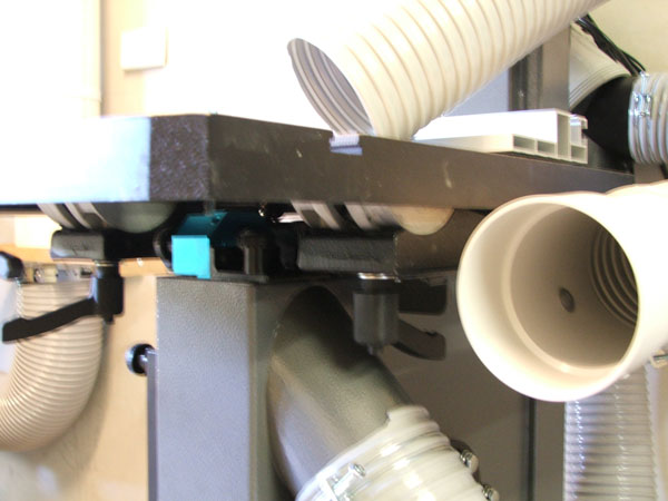
Below table with Hood removed.
Mounting bracket.
Mounting bolt inside the Flex adaptor.
New Hood with air steering flaps to keep air flowing over the guides and blade and between the Trunions.
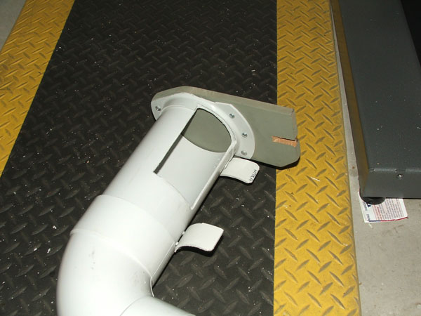
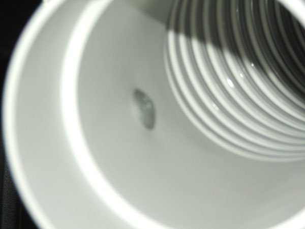
Size of opening is 72mm x 124mm.
-
16th February 2016, 05:56 PM #74
.
- Join Date
- Feb 2006
- Location
- Perth
- Posts
- 27,790
Good work.
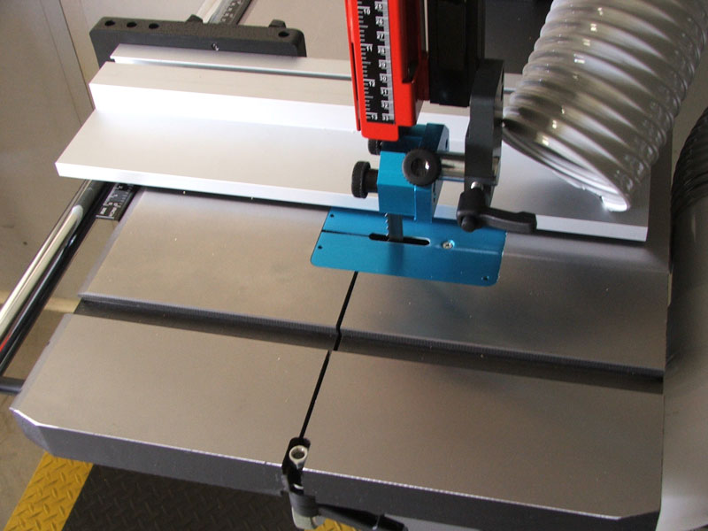
Have you considered some holes in the throat plate - maybe make another one up and keep the originals.
They won't pass a lot of air but it all adds up
Throatplate.jpg
-
16th February 2016, 07:57 PM #75
Supporting my wife's hobby.
- Join Date
- Nov 2013
- Location
- Caboolture QLD AU
- Posts
- 781
Thanks Bob, I was wondering about that, I read somewhere that it was not really worth it, but I guesss you don't know until you try, as I was going to make another plate in any case, I'll give that a go.
I'm just waiting for a Carter Blue tyre to arrive as the first replacement for a faulty Laguna tyre did't fit, so can't do any real thick cutting until then.

 Reply With Quote
Similar Threads
-
For forum members only.
By nt900 in forum FESTOOL FORUMReplies: 2Last Post: 1st November 2011, 06:55 AM -
How many forum members ....
By Incoming! in forum WOODIES JOKESReplies: 16Last Post: 4th September 2008, 05:43 AM -
Forum has >20,000 Members
By dai sensei in forum ANNOUNCEMENTSReplies: 13Last Post: 3rd July 2008, 11:42 PM -
u.k. forum members
By jow104 in forum TRITON / GMCReplies: 1Last Post: 4th March 2004, 07:58 PM
