

 Thanks: 0
 Likes:
  Needs Pictures: 0
 Picture(s) thanks: 0
Results 61 to 75 of 105
-
8th September 2012, 07:13 PM #61
 The prize lies beneath - hidden in full view


- Join Date
- Oct 2010
- Location
- 1017m up in Katoomba, NSW
- Posts
- 10,668

Good stuff, thank you for all your input Bob. I'll get to it (tomorrow?) and put the results up.
-
8th September 2012 07:13 PM # ADSGoogle Adsense Advertisement
- Join Date
- Always
- Location
- Advertising world
- Posts
- Many
-
8th September 2012, 07:28 PM #62
The prize lies beneath - hidden in full view
- Join Date
- Oct 2010
- Location
- 1017m up in Katoomba, NSW
- Posts
- 10,668
What I will do is use a Youtube that is 1m each side, and I'll seal the end after I have put the water in (leaving about 500mm of air space). That way the air that is trapped will be at relative atmospheric pressure, and movement up the other side will leave something to work on for the sealed side. Originally Posted by BobL

I think that this may tell me everything I need to know. For example, if there is a 50mm rise in the water level with a 1m vac hose, and a 40mm rise with a 3.5m hose then that tells me that the hose length is eating up suck power. Then, if I go to the various points in the system I'll know what the relative differences are between them and just hose direct to vac. A matter of playing with it to see what the results are, and possibly a little further discussion. I guess what I'm saying is that (without getting into equations) I should have some sort of handle on the pressure losses on the ducting system, and can also apply that to the new 50mm section to see how much difference the larger pipe makes.
-
9th September 2012, 01:08 AM #63
GOLD MEMBER
- Join Date
- Nov 2006
- Location
- Rockhampton
- Age
- 62
- Posts
- 2,236
Originally Posted by FenceFurniture
 Read the question Pete, Read the question.....
-
9th September 2012, 06:01 AM #64
 .
.
- Join Date
- Feb 2006
- Location
- Perth
- Posts
- 27,806
If you close the end of the manometer you will have no way of comparing results with others - as long as you know that.
-
9th September 2012, 05:46 PM #65
The prize lies beneath - hidden in full view
- Join Date
- Oct 2010
- Location
- 1017m up in Katoomba, NSW
- Posts
- 10,668
A very interesting afternoon
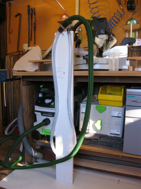
OK! Today I made a Womanometer (it's a manometer with one end shut off to further discussion). It cost me $12, and has provided some very interesting information indeed. I used a plumb, Bob, to make sure everything was vertical. As you can see, the tubes has some bends in it, but they are all pretty symmetrical, and we should not forget that this is only relevant to my system, and that what I am trying to determine is how much suck is lost to the ducting and the cyclone in rough figures.
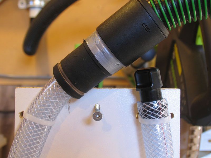
Here is the business end, and you can see that one side is trying to suck information out, and the other is shut down, and won't budge (so which is the male and which is the female..hmmm? )
)
I took several measurements of different combinations, and the results are really interesting.
Bob, for the purposes of demonstration, I'm going to assume that the following results can be expressed linearly, and not with some mongrel of a logarithm involved, but your input is always welcome on such matters.
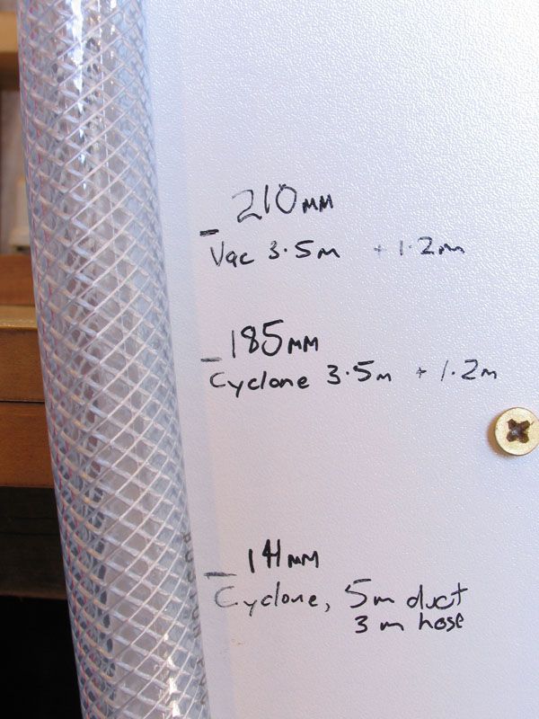
Measurements
1. A 3.5 metre hose direct to the vac lifted the water 210mm
2. A 1.5 metre hose direct to the vac lifted the water 210mm
........that is to say that the hose length made NIL difference
3. A 3.5 meter hose connected via the Cyclone lifted the water 185mm
4. A 1.5 meter hose connected via the Cyclone lifted the water 185mm
........that is to say that the Cyclone reduces the suck by 12% (and quite acceptable for the benefit that it gives IMO)
5. At the furthest point from the Cyclone (the drill press end) the air is going through 5 metres of 40mm water pipe, 3 metres of corrugated hose, and two diverters. The water was lifted by 141mm
....... that is to say that I have lost 33% of the total suck available at the weakest point of the system. This is totally acceptable (and around what I thought it would be) based upon the extraction results that i have been getting.
A control reference:
I went back to just the 3.5 metre hose direct to the vac, and turned the power down to zero. Then, I wound the Vac power up until the water reached the Drill press level, and I'll be damned if it wasn't about 66% (which correlates perfectly with the lineal results showing a 33% loss).
Don't worry Bob, reckon your day-job is still safe from me!
-
10th September 2012, 01:20 AM #66
GOLD MEMBER
- Join Date
- Nov 2006
- Location
- Rockhampton
- Age
- 62
- Posts
- 2,236
Hi Brett,
From what you have written and as I understand it you have made several tests (long/short hose/cyclone etc) with the vac hose by itself then with additional components in series plumbed direct onto the end of one end of the tube with the other end plugged, my initial thinking is that will only show a max value (210mm) and then the lower values only show that there are leaks as more components are added,
Is this what how you tested or am I not with it?
Pete
-
10th September 2012, 01:44 AM #67
The prize lies beneath - hidden in full view
- Join Date
- Oct 2010
- Location
- 1017m up in Katoomba, NSW
- Posts
- 10,668
Nearly Pete. The right side of the Womanometer was always blocked off (in fact it'll need tools to unblock it after all the tests). Then I just plugged various intakes (or pick up points if you like) in the ducted system into the other side of the tube. This means that there was a constant mass of air in the sealed side, but this mass got distended to different pressures and volumes. To be clear, this series of tests was done with a sealed tube so that I didn't have to use a 5+ metre unsealed tube (2 x 2.5) to conduct the tests.
Edit: I think I may have slightly misread your post Pete. We've both just said essentially the same thing. But it wasn't so much to find leaks (which are clearly there btw) as to see how good or not the end result was on paper (as I already know that it does the job, regardless of how much is lost). I guess you could say that I'm quantifying my initial findings.
-
10th September 2012, 08:14 AM #68
GOLD MEMBER
- Join Date
- Nov 2004
- Location
- Millmerran,QLD
- Age
- 73
- Posts
- 11,156
Brett
To answer pete's question, I think you are measuring frictional losses caused by:
1. Diameter of the pipe.
2. Length of the pipe.
3. Internal roughness of the pipe (corrugated or smooth)
4. Leaks (which are unidentified)
This is all compared to the potential of the bare vacuum without any hoses attached, which provided the reference point.
A similar analogy with pressure as opposed to vacuum would be the garden hose. A standard 20m, half inch garden hose will give a certain pressure and flow. Increase that hose to 200m and barely a dribble will be seen at the end.
Sorry for stating the obvious. It's what I do. (Where are the smilies? I know the're there somewhere!)
Regards
PaulBushmiller;
"Power tends to corrupt. Absolute power corrupts, absolutely!"
-
10th September 2012, 06:45 PM #69
.
- Join Date
- Feb 2006
- Location
- Perth
- Posts
- 27,806
Firstly - Excellent work FF.
The fact that the tube has bends doesn't matter a bit Originally Posted by FenceFurniture
Yep - no problem - it's a pity it's not done with an open end so some external comparison could be made.Bob, for the purposes of demonstration, I'm going to assume that the following results can be expressed linearly, and not with some mongrel of a logarithm involved, but your input is always welcome on such matters.
While the way you are doing the measurements may provide something of use, it's not going to provide the info you are after.
This is why you are not seeing any differences in pressure due to changes in the length of pipe.
What you are doing is called a static pressure measurement.
Up to a point It won't matter low long the ducting is or whether it's corrugated or if it has right angle bends or not, the pressure in the duct changes at the speed of sound to a static equilibrium inside the pipe and it should be whatever the vacuum cleaner can generate. Because you have a closed end manometer, the pressure in the air trapped at the closed end of the manometer = the pressure the CT36 can generate (24000 Pa).
To assess pressure losses n pipes the pressures should be measured inside the pipe "while the DC/vacuum cleaner is drawing its normal load of air" ie perform a dynamic measurement.
This means tapping into the side of ducting so that the air is moving past it and attaching the manometer to that and having the other end open to the atmosphere.
The fact that you have a different pressure when adding your cyclone is almost certainly because it has leaks. If it was airtight your reading should be 210 mm.
This demonstrates very nicely another use for a manometer, ie finding leaks and everyone should have one.
To get some idea of what to expect I just tried your expt with 38 mm diam PVC and my open ended manometer connected to a 30 year old elcrapo vacuum cleaner I pulled out from under the house.
The pressure difference in the pipe at the vacuum cleaner end between a 30 cm length and a 1.3 m length of that pipe was ~20 mm.
I was also able to measure the air speed using my air flow meters.
Its a difficult measurement because it is a small pipe but I did a few measurements and got ~25 m/s this translates to a volume of 60 cfm (is it is an old battered vacuum cleaner)
Then plugging all this into static pipe calculator it says I should see a pressure loss of ~24 mm - given my setup is quick and dirty so it must have leaks and the airflow measurement is difficult I am surprised theory and practice line up so well.
Would you like to see a pic of my setup?
-
10th September 2012, 07:00 PM #70
The prize lies beneath - hidden in full view
- Join Date
- Oct 2010
- Location
- 1017m up in Katoomba, NSW
- Posts
- 10,668
Good on you Bob. Yes, I certainly like to see a pic if it's not too much trouble.
-
10th September 2012, 07:41 PM #71
.
- Join Date
- Feb 2006
- Location
- Perth
- Posts
- 27,806
Here is the setup.


BTW if you decide to use those little plastic taps they have an angled ends then the orientation of the angle needs to be the same for consistent measurements. To get an accurate static pressure reading a right angle needs to be added on the inside of the pipe so that the opening of the right angle faces forward into the flow. Have a look at BPs measurement of static pressure page here. You can see on that page how he talks about using a manometer to test for leaks etc.
It is really important that there are no leaks in any of the joints so I use a little loctite between the PVC and the PE tap threads and vaseline on the black pipe..
-
10th September 2012, 07:59 PM #72
The prize lies beneath - hidden in full view
- Join Date
- Oct 2010
- Location
- 1017m up in Katoomba, NSW
- Posts
- 10,668
That's nice and neat Bob.
-
10th September 2012, 09:01 PM #73
.
- Join Date
- Feb 2006
- Location
- Perth
- Posts
- 27,806
Cheers FF - I forgot to add some extra (important) info to my post above but I have fixed it now. Originally Posted by FenceFurniture
Also if you can tell me the length of your original air column on the closed end of you manometer was I might be able to work out what actual pressure 210 mm corresponds to.
-
20th January 2013, 01:56 PM #74
Member
- Join Date
- Feb 2012
- Location
- Sydney
- Posts
- 75
Hose sizes between vac, DD and tool
May I please resurrect this thread? In FF's post of his setup on 28/8/12, there is ?37mm hose (Carbatec, ribbed lining?) between vac and DD, and possibly 27mm from DD to tool.
I've got the same vac (thank you Brett), and cyclone (though home-made collector), and wish to collect from a Metabo ROS, which has a 32mm ID (36mm OD) take up point (the Fein triangular sander fitting is identical).
Theoretically, 50mm smooth-lined hose as far as possible should maximise efficiency (with vac set on 50mm hose), but that creates a choke point at the tool, which I assume will seriously impact efficiency.
Should I therefore use 37mm throughout, with vac on '36' setting to maximise match between hose/tool uptake diameter and vac pressure/flow? Alternatively, use 50mm to DD, then 37mm (or is that neither my a nor my elbow)?
Thanks
Mark
-
20th January 2013, 02:31 PM #75
The prize lies beneath - hidden in full view
- Join Date
- Oct 2010
- Location
- 1017m up in Katoomba, NSW
- Posts
- 10,668
Hi Mark, I'm not sure if i can answer all of your question, but between vac and cyclone is 50mm hose which came with the cyclone. All the other hoses you can see are 27mm. I should be using a 36mm from the ducting outlet to the cyclone, but that's all I had then.
As far as hose diameters for various tools goes - Bobl would know more than I, but the hose dia depends on the tool/particle size, and how high the air velocity is required to be (I think the finer the dust the higher the velocity needs to be).


 Reply With Quote

Similar Threads
-
A happy chappy
By watsrags in forum WOODTURNING - GENERALReplies: 3Last Post: 26th September 2009, 02:27 PM -
Ducting
By K>60 in forum DUST EXTRACTIONReplies: 11Last Post: 18th September 2007, 09:43 PM -
Shop-made edge sander, Shop Notes #37 article
By Jonthechippy in forum Links to: BOOKS, VIDEOS & PLANSReplies: 3Last Post: 14th June 2006, 05:10 AM -
Ducting Costs
By Grunt in forum WOODWORK - GENERALReplies: 1Last Post: 13th July 2004, 10:13 PM
