

 Thanks:
  Likes:
  Needs Pictures:
  Picture(s) thanks:
Results 1 to 15 of 30
-
22nd April 2024, 11:51 AM #1
 SENIOR MEMBER


- Join Date
- Mar 2009
- Location
- Sydney
- Posts
- 538
 Improving the dust extraction from my Hammer K3 TS
Related to my new extraction project which is inching ahead.
This is what I pulled out of the undersized (to my thinking) flex inside the machine.
It's regular thing.
Questions:
1. When I connect the 150mm ducting to the back of that machine I'm anticipating some of that stuff will go to the DC. Will it be a problem if slivers like that hit the fan?
2. Those Europeans are very clever, but has anybody had a go (successfully) at fiddling with the dust collection flex inside the machine? That throat under the blade seems very constricted.
Saw extraction.jpg
-
22nd April 2024 11:51 AM # ADSGoogle Adsense Advertisement
- Join Date
- Always
- Location
- Advertising world
- Posts
- Many
-
22nd April 2024, 01:00 PM #2
GOLD MEMBER
- Join Date
- Sep 2012
- Location
- Coffs Harbour
- Posts
- 1,809
 Originally Posted by scottbr

Welcome to my pain ha, I have recently replaced the internal dust collection flex hose on my C3-31, even though its a fairly recently model of 2016 the hose looked so disintegrated it convinced me something had eaten the plastic and left the copper. Then when i thought that Hammer and Felder sales would have a solution to the connection instead of forcing a rectangle housing into a 120mm tube i came across this thread in another Felder group im (and other members here) are apart of a few had some answers via 3d printing here . I saved one of the 3d files they provided and uploaded it into an australian 3D printer service as it fits the rectangular housing nicely for a 120mm hose or whichever hose you want to have it connect to for around $80-100aud.
I managed to fit the new hose around it as an interim connection and just recently fitted a zero clearance insert to help prevent long offcuts like in your photo from getting down there. I have to create another for the dadostack next.
Just going back to your first question though as to whether they can hit the fan of the dust extractor, answer is it depends. For me my current 2HP is under powered so it acts more as a "chip collector" and cant pull those long offcuts through so i occasionally find them in the internal pipe or nearby to remote. That being said im in the process of acquiring a cyclone which has a significant upgrade. In theory the seperation of larger offcuts going into the cyclone and falling down into the waste bin to keep successfully continue collecting the finer dust should take care of that from hitting the impeller but it depends on the cyclone design i think also.
Anyway, strong enough DC with separate chambers, 150mm piping and zero clearance inserts will put you into a pretty good position to tackle this though.
Looking forward to seeing your progress with this!
Cheers,
Nathan
-
22nd April 2024, 02:19 PM #3
SENIOR MEMBER
- Join Date
- Mar 2009
- Location
- Sydney
- Posts
- 538
Thanks Nathan.
So you did this:
''I saved one of the 3d files they provided and uploaded it into an australian 3D printer service as it fits the rectangular housing nicely for a 120mm hose or whichever hose you want to have it connect to for around $80-100aud.''
That's a bit beyond me, but I do know a bloke whose son is into 3D printing. I might have a chat to him.
Failing that I might have a crack at cobbling something together that would accommodate the excess 150mm flex I will have.
I'm not sure how a zero clearance insert would work on the slider side of the blade? That's where the problem 5mm gap is. I might just have to be a bit more vigilant at grabbing the offcuts before they head down below. Given I have a 3hp DC and there will be a straight run at knee height in 150mm PVC I fear any chunky off cuts will end up hitting the impeller. Still, that DC is 25 years old and came out of a factory, so It would have copped a fair bit of abuse before it ended up with me.
-
22nd April 2024, 02:38 PM #4
GOLD MEMBER
- Join Date
- Aug 2004
- Location
- Brisbane
- Posts
- 4,991
Ideally your table insert should be tight enough to prevent all but the thinnest slivers going into the guard. And you risk having to dismantle part of the ducting to get a blockage out. If they do get through the bends in the ducting you're unlikely to do any damage to a material-handling impeller. * edit I note your problem with zero clearance on your saw design
A word of caution about modifying a blade guard dust connection. Years ago I got advice to open up what sounds like a very similar arrangement on my Swedish Luna saw. The original connection took a 100mm flex and squashed it into a rectangle like yours. So I embarked on 3D modelling a new duct connection so that the 100mm could connect directly to the guard. The modelling took into account the shape so that I could still get the full range of depth and angle with the saw. The dust capture was dismally far worse than the original and because it was such a major modification, I could not set it back right without a lot of work. So I've just put up with it. I think the narrowing increases the air speed so it is more capable of diverting the very high speed dust off the saw. I wish I had never modified the guard. I also added a 100mm duct to the overhead guard which had nothing before. This was a very good mod. What I should have done was installed an additional 120mm duct into the cabinet and closed up the cabinet as much as possible. Since the mod, a friend also wound the spindle moulder into a position that conflicted with the saw depth and then stripped out the threaded brass bush on the depth adjustment which was quite a repair. Just to add insult to injury. So I would be very careful about modifying the guard.
-
22nd April 2024, 02:48 PM #5
SENIOR MEMBER
- Join Date
- Mar 2009
- Location
- Sydney
- Posts
- 538
Thanks for that note of caution, Mic-d. I understand what you mean
I've had a non invasive idea which I might play with over the weekend.
If it works, I will share it.
If it doesn't, we'll pretend it never happened.
-
23rd April 2024, 11:41 AM #6
GOLD MEMBER
- Join Date
- Sep 2012
- Location
- Coffs Harbour
- Posts
- 1,809
Originally Posted by scottbr
Hey Scott, Apologies that was a little light on detail. I have a 3d file named 'Hammer_hose_adapter.stl" that i have which i can email you as i cant upload it to the forums, All you do is upload that file to here 3D Printing Service Australia | Solidium3D Australia via the "upload model" button and you will see a little image of the model render in front of you. Then you just select the default settings to add it to your cart and purchase it to have it shipped to you. This model allows for the 45 degree tilt of the saw so wont crush the housing up against the internal K3 body.
I have selected solidium3d as its just a pay as you go service for 3d printing, i don't have own one or have anyone nearby to print it. If you do it would be worth doing a trial run as its likely cheaper.
with my zero clearance insert its literally hugging the blade both sides as you raise the blade through the insert when you install it so theres minimal chance anything will fall down into the inner pipe. My current 2HP dusty has a bit of a grill on the intake to stop larger pieces like that getting through but occasionally some still do. Hence the upgrade to a cyclone coming to hopefully separate that material in advance
Hope this helps.
Cheers,
Nathan
-
23rd April 2024, 12:10 PM #7
SENIOR MEMBER
- Join Date
- Mar 2009
- Location
- Sydney
- Posts
- 538
Yes please, Nathan. If you could email me that file that would be great. I'll send you a message with my email address.
There will be someone near me with a 3D printer, but if I have no luck I'll use that Melbourne company.
I'm curious about your 'zero clearance insert that hugs the blade both sides'. Is that a Felder/Hammer after market thing?
Otherwise I could probably fit a grill that would not impede airflow much but capture chunky bits before they hit the fan.
Scott
-
24th April 2024, 02:54 PM #8
.
- Join Date
- Feb 2006
- Location
- Perth
- Posts
- 27,800
Those slivers won't worry an impeller but they will eventually clog flexy.
Worse still if the clog and pile up sawdust and a stream of sparks (eg hitting a nail) hits the blockage it can start a fire.
This is what happened to my mate's Altendorf saw.
Fire3.jpg
-
24th April 2024, 03:19 PM #9
SENIOR MEMBER
- Join Date
- Mar 2009
- Location
- Sydney
- Posts
- 538
Geez. I can imagine a fire like that is something that could smoulder for a while before making its presence known. Originally Posted by BobL
Good to know the chunky bits won't hurt the impeller, though I might try and catch them before anyway - they would puncture a bag for sure.
I'll mostly finish my new dust line tomorrow and will take some photos on the weekend. You'll be pleased to see, Bob, that I'll have 150mm PVC going into the back of the saw cabinet.
-
24th April 2024, 04:18 PM #10
Be inspired. Be creative. Be bold.
- Join Date
- Apr 2001
- Location
- Perth
- Posts
- 10,830
Originally Posted by scottbr
Scott, my solution was to narrow the gap between blade and wagon with a section of aluminium ...
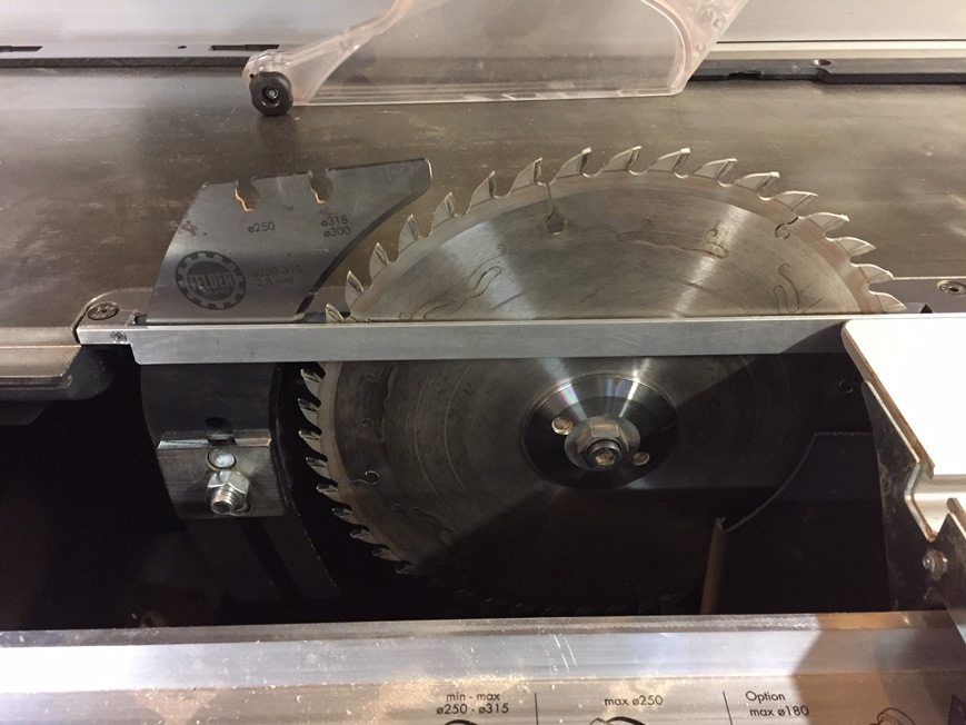

This has worked well for several years - any sliver that does get through is only paper thin. It, however, needs to return to the open insert for bevel cuts.
Regards from Perth
DerekVisit www.inthewoodshop.com for tutorials on constructing handtools, handtool reviews, and my trials and tribulations with furniture builds.
-
24th April 2024, 04:59 PM #11
SENIOR MEMBER
- Join Date
- Mar 2009
- Location
- Sydney
- Posts
- 538
That's a neat solution, Derek
So you took the existing insert and made an indent to accommodate some 3mm aluminium and then tapped those screws?
-
24th April 2024, 06:08 PM #12
Be inspired. Be creative. Be bold.
- Join Date
- Apr 2001
- Location
- Perth
- Posts
- 10,830
Scott, in one word, yes.
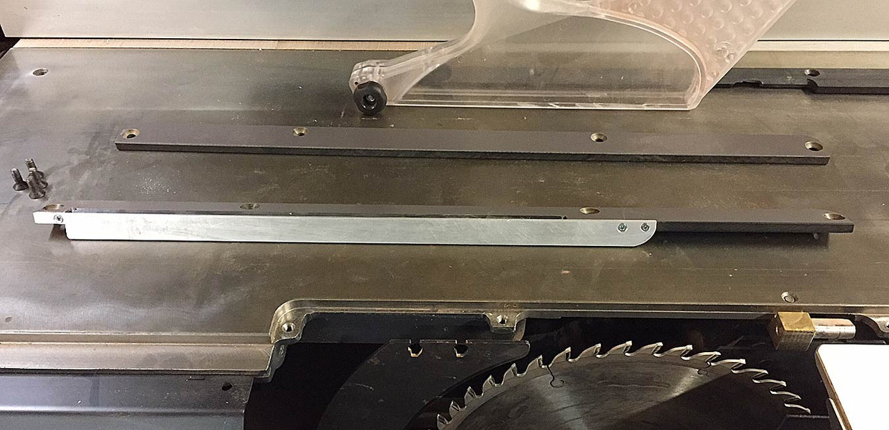
Here is a photo of the original insert (closest the camera) along with a blank sold by Felder as a ZCI for dado blades.

I used the blank to make a ZCI for a saw blade ...

However, the thin (plastic?) section along the wagon would vibrate with the saw spinning, and then it touched the blade and exploded!
So, a 3mm aluminium section was rebated into the broken insert and attached with epoxied and tapped screws.
The result is that the gap along the wagon is minimised ...
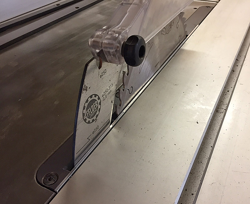
Recognise that the original insert has a gap equal to the "improved" insert less the aluminium filler section.
I plan to revisit this insert and all a horizontal section in aluminium about 10mm wide. This will run at right angles along the lower edge of the aluminium section here ...

This should further prevent any additional incursions. The logical way to do this is using angle aluminium (closing the side and an extending outward simultaneously).
Regards from Perth
DerekVisit www.inthewoodshop.com for tutorials on constructing handtools, handtool reviews, and my trials and tribulations with furniture builds.
-
26th April 2024, 11:09 AM #13
SENIOR MEMBER
- Join Date
- Mar 2009
- Location
- Sydney
- Posts
- 538
Originally Posted by derekcohen
Thanks Derek. I have that insert blank - came with the saw.
Silly question, but you use the saw to make the groove in the insert? What I mean is, you retract the blade. fit the blank, then bring the saw up through the insert to create its own slot?
And then presumably you extend the slot for the riving knife?
I guess that plastic or whatever it is would be no harder than some timbers, though I wish a had a cheap sacrificial blade.
-
26th April 2024, 11:49 AM #14
Be inspired. Be creative. Be bold.
- Join Date
- Apr 2001
- Location
- Perth
- Posts
- 10,830
Hi Scott
Start with the riving knife removed and the saw blade lowered fully. Screw in the plastic blank.
The saw blade is raised through the plastic blank. This will not harm the carbide tips.
Mark where the riving knife will fit, and remove the plate.
Knowing what I know now - that there is no point in trying to save the skinny plastic outer strip at the slot (it will vibrate and snap off) - saw it away now. This will make it easier to extend the slot for the riving knife. Choices here are a router, jigsaw, and files.
Attaching the aluminium side involves (1) shaping it and drilling the holes for screws, and (2) recessing the plastic for a flush fit.
The plastic can be tapped to create a female of the screw, but it is brittle and may not hold. I vaguely recall the fit being sloppy, and the screws held with epoxy.
I plan to make another ZCI, and this time the aluminium side will be L-shaped, with the horizontal edge running below the wagon, and about 25mm wide. That will close off all from dropping into the saw.
Note that the original insert shiuld be retained to use when sawing a mitre - when the blade is angled, it will otherwise contact the aluminium.
Regards from Perth
DerekVisit www.inthewoodshop.com for tutorials on constructing handtools, handtool reviews, and my trials and tribulations with furniture builds.
-
26th April 2024, 12:49 PM #15
SENIOR MEMBER
- Join Date
- Mar 2009
- Location
- Sydney
- Posts
- 538
Those instructions are very clear, Derek.
And I understand what you mean by using an angle on your ZCI Mark 2.
I'm pondering a slight variation.
I have some 12mmx12mm x 1.6mm aluminium angle.
My new plan is to epoxy and screw it to the edge of the blank before I bring the blade up through it. So on the carriage side of the blade I will still have that thin strip of plastic and the angle.

 Reply With Quote


Similar Threads
-
Improving dust extraction for C26 Advice Requested
By WoodyOwen in forum DUST EXTRACTIONReplies: 2Last Post: 28th June 2021, 04:38 PM -
Hammer K3 Improving dust collectionmm and then into
By AJ. in forum DUST EXTRACTIONReplies: 18Last Post: 7th February 2021, 04:45 PM -
Dust extraction on Hammer K3 slider
By ronboult in forum DUST EXTRACTIONReplies: 7Last Post: 23rd September 2020, 07:52 PM -
Cabinet Dust Extraction On a Hammer Slider
By Chris Parks in forum DUST EXTRACTIONReplies: 1Last Post: 23rd October 2016, 09:59 PM -
Improving the dust extraction on a generic drum sander?
By KBs PensNmore in forum DUST EXTRACTIONReplies: 5Last Post: 11th May 2016, 11:44 PM
