

 Thanks:
  Likes:
  Needs Pictures:
  Picture(s) thanks:
Results 1 to 8 of 8
-
22nd November 2012, 12:48 AM #1
 GOLD MEMBER


- Join Date
- Nov 2006
- Location
- Rockhampton
- Age
- 62
- Posts
- 2,236
 A look inside some dust extraction ducting
I am moving a few machines around in the man cave which has meant a bit of dust collection ducting rejigging, I got to a point and had one of those moments where I say to myself "that would look interesting" as you do
 .....If I have this right we might see a vid of some dust being sucked up out of a bucket into the ducting via one inlet furthest away from camera, I then try the closest to the end and then I draw away showing a view of dust continually swirling around the end of duct where I have clamped a piece of perspex, I suspect this is an area of lower pressure and dust gets sucked backwards towards a no flow region (the blanked of end) dust collection ducting - YouTube
Pete
-
22nd November 2012 12:48 AM # ADSGoogle Adsense Advertisement
- Join Date
- Always
- Location
- Advertising world
- Age
- 2010
- Posts
- Many
-
22nd November 2012, 06:07 PM #2
.
- Join Date
- Feb 2006
- Location
- Perth
- Posts
- 27,794
Nice Vid Pete. Originally Posted by pjt

That's a pretty normal event with DC type air movement. If that dust is not cleared while it is still loose and friable, when the DC is switched off it may fall to the lowest level in the ducting and if it repeatedly gets damp (just some moist air) over a few days it can stick to itself (and also the ducting) thus restricting the duct. This is another reason why, after the last dust making activity, all ducts are opened up to vent the shed and ducting.
-
24th November 2012, 01:22 AM #3
GOLD MEMBER
- Join Date
- May 2010
- Location
- Not far enough away from Melbourne
- Posts
- 4,204
Great video indeed Pete, a lot of food for thought there. I have watched the dust spiraling like that through the only (partly) transparent pipe I have which is flexible hose and have assumed that the spiraling is at least partly associated with the rib in the hose, not that you get a really good look at it. I did not think that spiraling induced by the impeller would extend any serious distance up the pipe at all. Or is the airflow up the pipe not spiraling but the dust particles are within that stream because of their inertia and angle of entry? or a combination of both?
Its too late at night/early in the morning and I am on holidays. I need to review this one and consider its implications another night in an environment with a lesser influence of maroon cans.
DougI got sick of sitting around doing nothing - so I took up meditation.
-
25th November 2012, 02:00 AM #4
GOLD MEMBER
- Join Date
- Nov 2006
- Location
- Rockhampton
- Age
- 62
- Posts
- 2,236
 The spiral we see there I'd say is induced by the offset of the inlet pipes rather than by the fan, I purposely made the transitions this way, my main is 200mm and the inlets are 120mm which means they are offset by 80mm rather than be on centre, (40mm each side) with on centre transitions there is more tendency for particles/air to impact the farside of the main pipe, I have observed this when setting up for this vid., with the airflows and speeds we have turbulent flow so my thinking was that a spiral induced airflow might be a way of controlling the turbulence to some degree, potentialy more friction involved tho, just a guess on my part.
So far I have made all my transition inlets at 45� (just as a standard) the angle has an influence on the spiral, a lesser angle would give less of spiral, the benefit tho is for slightly better airflow.
Just another note... the video needs to be rotated 90� clockwise, I thought i might have been able to do that but I couldn't, the point where the dust dissapears is into a 45� tee which looks good to me.
Pete
-
26th November 2012, 05:53 PM #5
.
- Join Date
- Feb 2006
- Location
- Perth
- Posts
- 27,794
This is the same effect as a duct bend where the flow is thrown hard up against the back of the bend or a junction thereby causing more friction. But unless really wide radius bends or ports are utilised this is inevitable. So the message here is try to keep the ducting changing direction as little as possible. Evidence for this effect is when measuring the flow in the middle of a duct downstream of a bend or inlet. What I often observe is the airflow varying in time with a period of 10 - 20 seconds due probably to small variations of input flow angle moving the flow around as per this diagram (the air itself acts like a flicking ribbon within an airstream). At the probe the air speed increases and decreases in a semi-systematic manner which makes air flow measurements a pita. Measuring at least 10 duct diameters down stream of junctions is recommended but not always possible. Originally Posted by pjt
-
27th November 2012, 02:48 AM #6
GOLD MEMBER
- Join Date
- Nov 2006
- Location
- Rockhampton
- Age
- 62
- Posts
- 2,236
a few more views of inside ducting
Yes, as Bob says some things are inevitable, death and taxes
and dust so, in the dust collecting pursuit I have three vids for the viewing, all 3 are in a different section of main ducting with only one 120mm dia. inlet and then coupled onto a 45� and the orientation is as viewed, the difference between the vids is the fitting (90�, 45�, 90�+pipe) close fitted to the end of the transition inlet pipe.
All fittings/pipe are standard off the shelf 100mmDMV
To see what is going on I simply offer up to the fitting a bucket of dust and try to maintain a steady stream of dust, to get a big load of dust I bury the fitting in the bucket which soon gets sucked up quickly, also I had to leave a gap between perspex and 200mm pipe so dust doesn't block the view, which is the majority of the noise
First the 90� elbow, what we see is the majority of the dust exiting the top of the inlet, this suggests to me that the sharp radius is forcing the dust/airflow to the outside of the elbow and we then see this as the dust exiting the top of the pipe
90� inlet - YouTube
Next I tried a 45� instead of the 90�, maybe a little bit better but not much IMO
45� inlet - YouTube
Next was a 300mm long bit of 100mm pipe fitted to the inlet with a 90� on the end of that, to my eye this looks like the flow has moved towards laminar, (just like Bob's diagram depicts above) with dust now exiting the whole of the 120mm pipe
90� with a 300mm long pipe - YouTube
and a pic of the final setup
300mm pipe plus ninety.JPG
A few offerings in conclusion, the standard off the shelf 90� is too short a radius for the amount of air I amwe moving and the positioning of fittings/pipe can have a detrimmentl effect on flow
Pete
-
27th November 2012, 03:04 PM #7
.
- Join Date
- Feb 2006
- Location
- Perth
- Posts
- 27,794
Pete after seeing your video it reminded me of some experiments I did a few months ago and never got around to reporting on, and that was the effect on air flow of different reducers/adapters from one duct size to another. The reason I did not report on it was the measurements appeared to be all over the place but now that I have gone back and looked at them again there may be a problem with some types of reducers.
What the the theory and BP says and we basically already sort of know and that is that reducers should have a long taper and be symmetrical, otherwise they will generate turbulence.
Below are the main type of PVC reducers I use on my system to go from 4" up to 6" ducting.
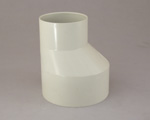
They are neither symmetrical, nor do they have a long taper.
When I test air flow anywhere near these reducers I detect a very large amount of turbulence, hence measurements of CFM using these in the system become a PITA and take a long time.
The other reducers I have used to reduce from 6 to 4" are sheet metal and have a 300 mm long taper.
Looking back on the data it suggests that the stubby PVC type reducers also generate about 10% less flow compared to the longer tapered ones. It could even be more than this but that is all I can say with the data I have at the moment. I will do the measurements again to see if I can get more reliable data.
I wonder if the turbulence is caused more by the asymmetry or by the short taper?
Has anyone managed to find symmetrical PVC reducers of any kind
-
28th November 2012, 12:00 AM #8
GOLD MEMBER
- Join Date
- Nov 2006
- Location
- Rockhampton
- Age
- 62
- Posts
- 2,236
Can't say I have seen anything like we ideally want, reducers that are symetrical but with no taper, for water and using gravity plumbing fittings can be less than ideal for what we need
Pete


 Reply With Quote
Similar Threads
-
Dust Extractor ducting, 5 or 6 in?
By zelk in forum DUST EXTRACTIONReplies: 12Last Post: 29th November 2012, 11:57 PM -
90mm ducting for dust extraction ?
By Arron in forum DUST EXTRACTIONReplies: 16Last Post: 16th August 2012, 06:21 PM -
Dust Extractin Ducting
By Chris Parks in forum DUST EXTRACTIONReplies: 5Last Post: 20th January 2008, 05:13 PM -
ducting for dust extracting
By jow104 in forum WOODWORK - GENERALReplies: 5Last Post: 21st April 2004, 06:16 PM
