

 Thanks:
  Likes:
  Needs Pictures: 0
 Picture(s) thanks: 0
Results 1 to 13 of 13
-
22nd November 2014, 12:45 PM #1
 Senior Member


- Join Date
- Jul 2007
- Location
- Narnia
- Posts
- 113
 My Great Big 1905 MkII** Ross Rifle Project
My Great Big 1905 MkII** Ross Rifle Project. (....... Or how to build a Ross rifle from scratch because "Bubba" sporterised (bastardised) it long ago)
Recently picked up a 1905 MkII** Ross Rifle .303 that has at some time in its past been seriously "got at", and as a result there's an amount of work and (unobtainable) componentry required to get it back to something nearing its original condition.
The rifle is actually the "Target" variant, fitted with quite a rare BSA Martin micrometer rear sight, and would have been the same model that did so well @ Bisley in its day.
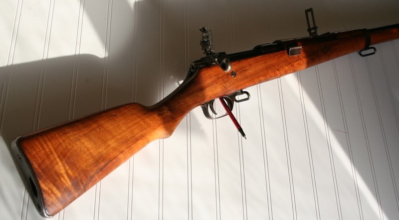
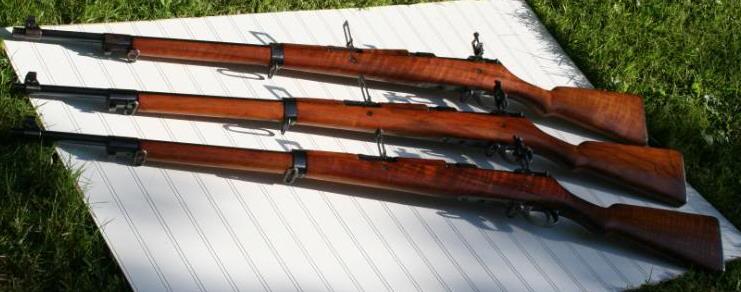
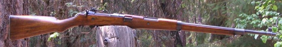
Heres some pics of roughly what it should look like when the whole thing is finished..... (Disclaimer these aren't my rifles, though I wish they were - these are reference/ inspiration pics )
)
......but between now and then I've got to obtain some unobtainable trinkets :facepalm: :
[list]
-MkII** Nose Cap (to suit the heavier profile barrel)
(working on the bayo lug - see below)
-Rear sling swivel(working on this)
- Bolt that retains the middle barrel band
-MkII front sight assembly(Just need some dimensions for the sight hood)
-"Keeper Ferrule"
Now given there's not been a ross made in close to 100 years, and that these same items are the ones everyone seems to be looking for: I'm very realistic about the prospects of tracking some of these parts down - so I'll be looking to machine/fabricate any of those which I can't source in the meantime.
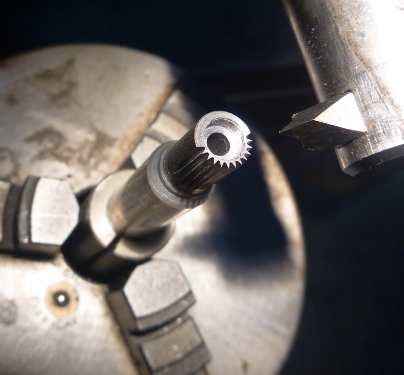
The first of those parts I've resorted to making is the serrated "keeper Ferrule" (not sure of the official Ross Nomenclature) that engages the twin front action screws of the MkII ross (assumedly to prevent the screws loosening under recoil) . Had been told these tiny little pieces are virtually unobtainium, and can certainly imagine these'd be the first item lost once a rifle's been disassembled a number of times and in reality its probably of questionable necessity to rifles machinations anyway.
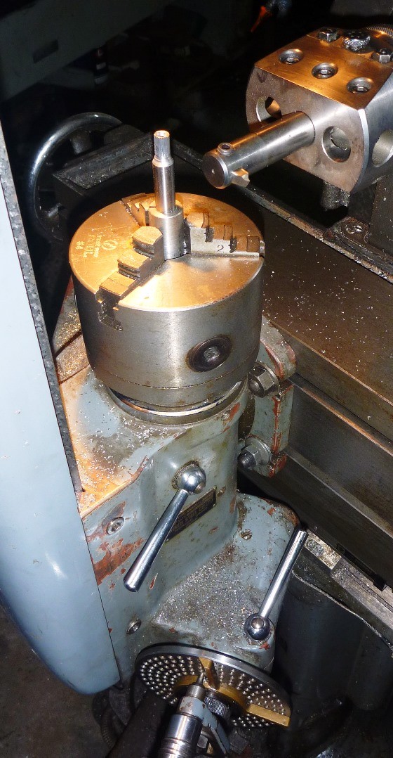
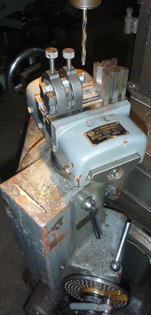
Mill set up in horizontal guise with the dividing head
Close up of the machining details
Note: The split magazine box and twin front action screws (and serrated keeper) necessitated by the arm of the Harris follower being on the centre line of the action.
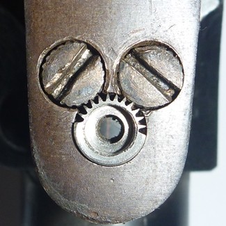
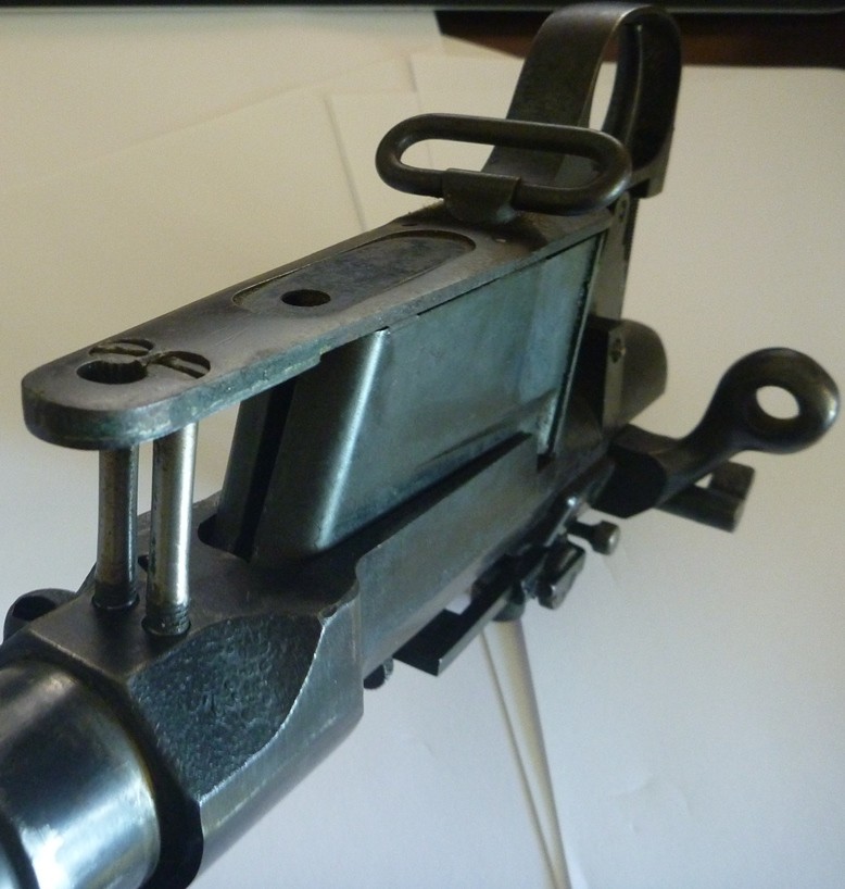
The "Keeper" installed in its pocket, engaging the other screw heads.
The heads of these action screws are visibly mangled so if these can't be tidied up a bit, I may resort machining some replacements of these too (slippery slope, I know).
Now I'm not holding out much hope that anyone here is overly familiar with a Ross Rifle, but on the off chance I'd be eternally grateful for any expertise that may be lurking around the forum.
Don't suppose anyone knows the dimensions of the little bolt that holds the "keeper"?WANTED: D1 - 8" Camlock either on a backing plate, or drive plate
DECENT CONDITION, REQUIRED FOR A PROJECT - SEND ME A PM IF YOUR ABLE TO HELP
-
22nd November 2014 12:45 PM # ADSGoogle Adsense Advertisement
- Join Date
- Always
- Location
- Advertising world
- Posts
- Many
-
22nd November 2014, 12:46 PM #2
Senior Member
- Join Date
- Jul 2007
- Location
- Narnia
- Posts
- 113
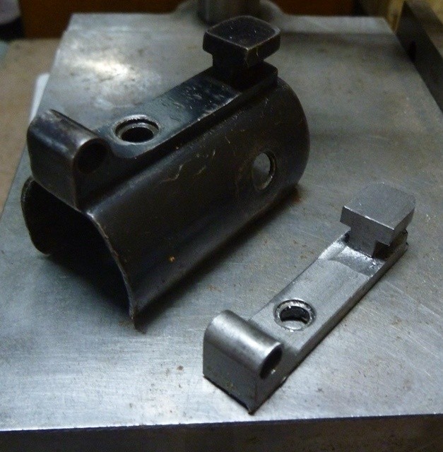
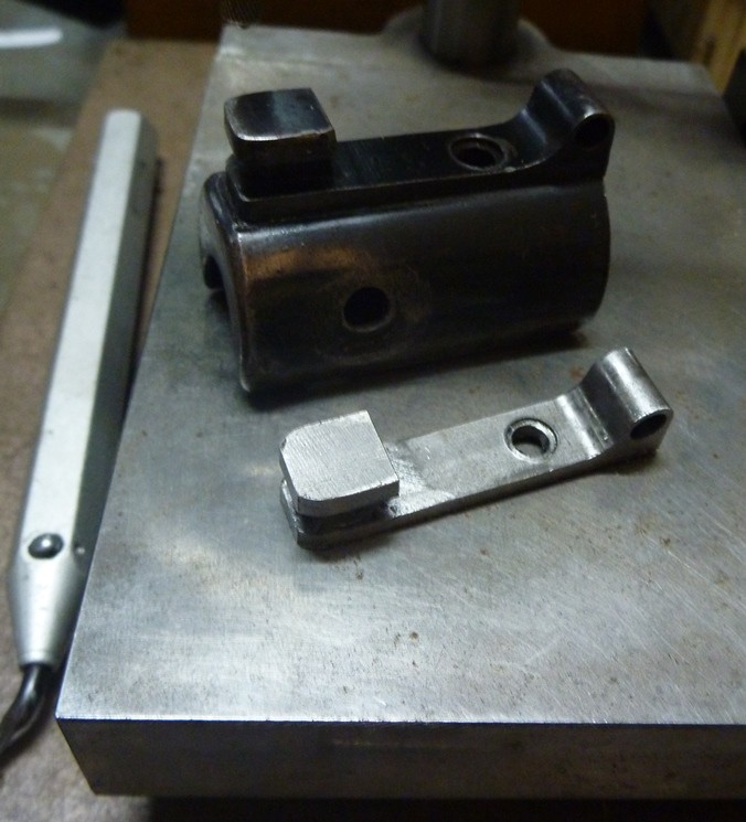
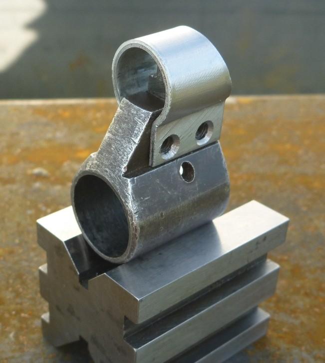
"Bubba" also decided he needed to cut the top off the nose cap?
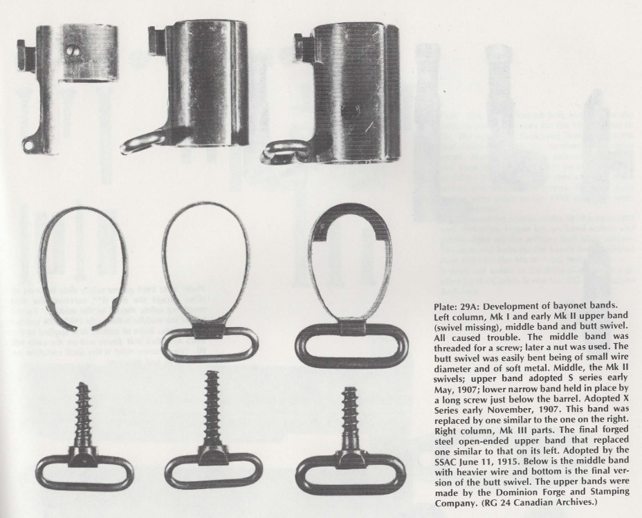
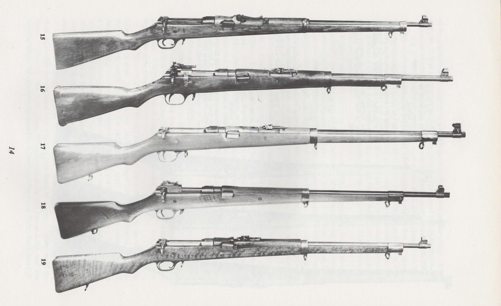
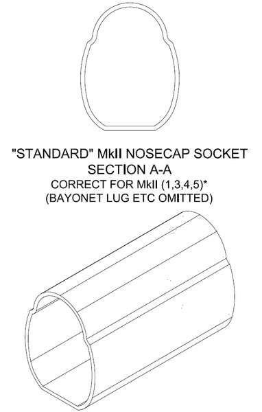
Excerpt from the ross rifle book showing the evolution of the various fittings; those in the centre column are of the correct era for my MKII**
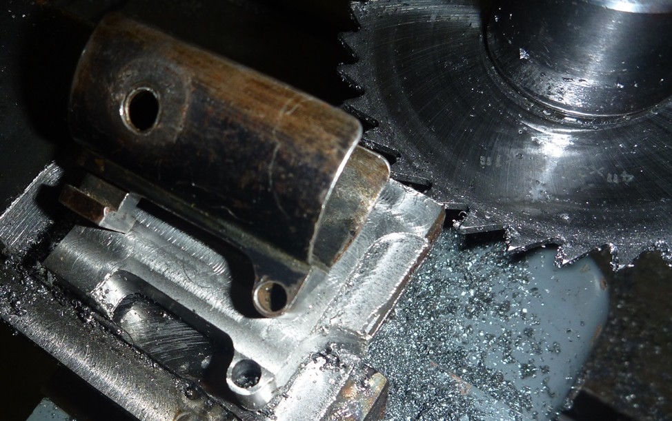
Roughing out the profile & then parting
Undercutting the lug
Parting off with a slitting wheel
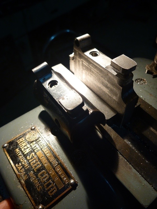
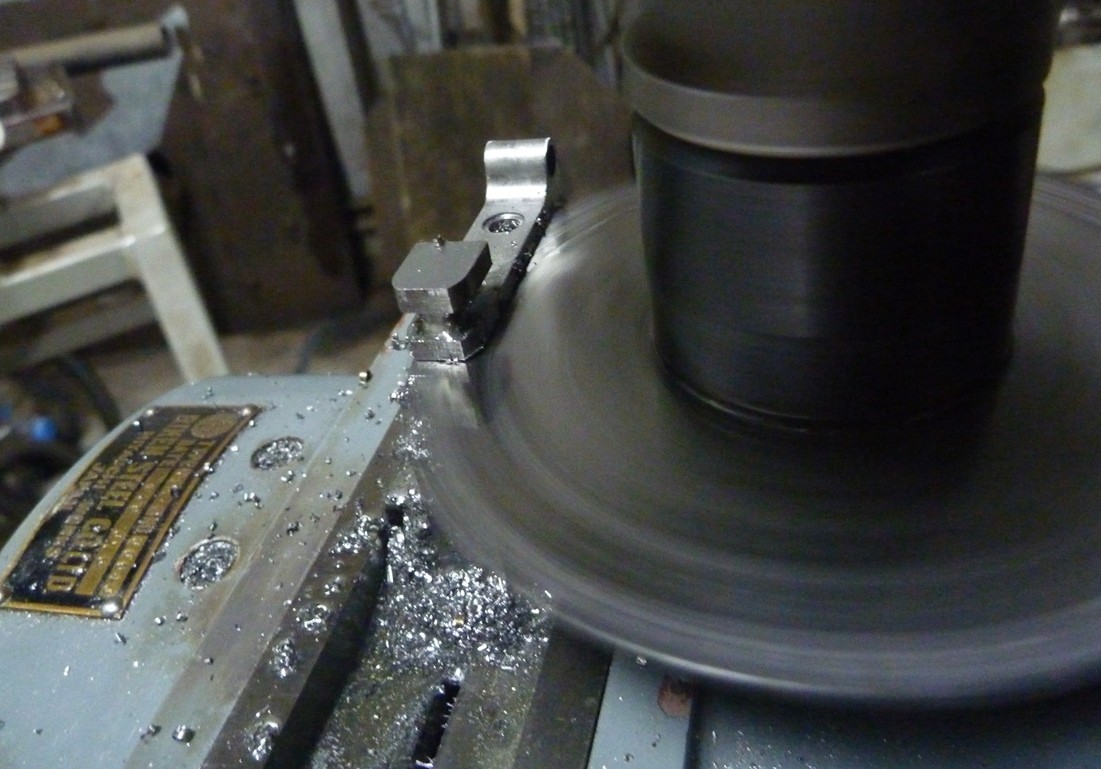
The completed lug, now need to de-burr and work out just how i'll go about the forming & fabrication of the nosecap.
Among the bits my rifle is missing is the rear sling swivel, so here's me working to rectify this:
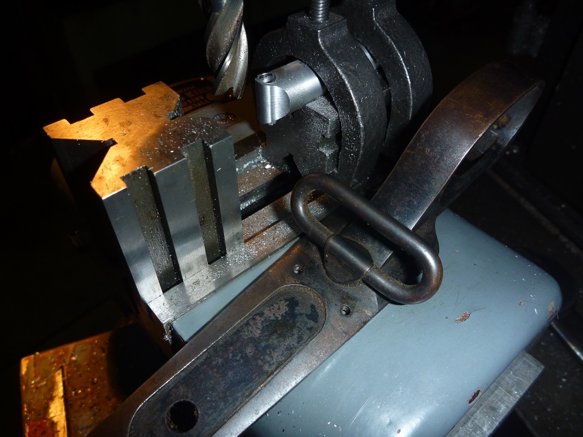
Using the dividing head to machine the wave shape on the rear sling swivel head. I used the existing target swivel attached floor plate as reference for the dimensions & styling etc
 WANTED: D1 - 8" Camlock either on a backing plate, or drive plate
DECENT CONDITION, REQUIRED FOR A PROJECT - SEND ME A PM IF YOUR ABLE TO HELP
-
14th February 2015, 10:00 AM #3
.
- Join Date
- Nov 2008
- Location
- Perth WA
- Age
- 71
- Posts
- 5,650
Great work Glen!

I like your use of the boring head to hold the spline cutter. Is the dividing head mounted vertically simply because you have that whizzo vice and you can perform most tasks with that setup?
Bob.
-
15th February 2015, 09:53 AM #4
Senior Member
- Join Date
- Jul 2007
- Location
- Narnia
- Posts
- 113
Hi Bob,
yeah the 2 jaw chuck/vice for the dividing head adds a hell of a lot of versatility and as an estimate the mill has probably spent 70-80% of its time recently set up in that configuration, probably because those are the types & size of projects I've had. Have got some keyways to cut in shafts and plate boring so will be swapped back over to the table soon - suppose its a bit seasonal really as what form my mill takes (ideally I need a second one ) so most jobs can be done without to much swapping of attachments
I love it, but can certainly see the advantage of cnc when it comes to jobs involving radii & multiples of, one certainly tires of coming up with new and pithy ways to bring the centreline of the radius, onto the centre of the dividing head spindle axis.
A member of the ShootingAustralia.net forums, magnificently offered to lend some of the missing componentry for measurement/duplication purposes - so a massive thankyou goes out to him for his generosity and his patience whilst the reverse engineering/nutting out process crawls along.
The protective hood for the front sight was discarded from my rifle long ago and after some research it turns out they are right up there (along with MkII nosecaps) on the list of most requested ross rifle trinkets in the various milsurp classifieds. Those that have them aren't selling and Ross Rifle Co certainly isn't making any more so figured I could do something about it and help others out too.
These are the jigs, I came up with to assist in the making of Ross sight hoods. Fortunately the hoods used on the MkII's & MkIII's are dimensionally the same, so the one set of tooling caters for both models.


The number drills will be replaced with tool steel of the appropriate gauge, initially was just keen to see if the concept would even work.

Have had to skim some material down to match the thickness of that originally used, otherwise the mean diameter would be wrong for the developed shape/layout.
So long term will need to chase around and see what can be sourced - am hoping .0525" is a common gauge in some of the imperial speaking country's.

Still need to de-burr a little and investigate blueing etc but think the result looks promising at this point.
I'd also been sweating on finding the correct barrel dimensions for that variant, so I could let the barrel maker know.
A massive thanks goes out a few members on the rossrifle.com forums they were able to measure the contours of the heavy barrels on their MkII**'s for me, and here's the resulting drawing.

I did add a little to the tennon length to match the other ross barrel drawings I've seen - far easier to remove material, than add it back on
(disclaimer the PDF formatting of my CAD program, is playing up quite a bit and leaving bits out?)WANTED: D1 - 8" Camlock either on a backing plate, or drive plate
DECENT CONDITION, REQUIRED FOR A PROJECT - SEND ME A PM IF YOUR ABLE TO HELP
-
15th February 2015, 10:18 AM #5
.
- Join Date
- Nov 2008
- Location
- Perth WA
- Age
- 71
- Posts
- 5,650
Wondrous stuff Glen. A true craftsman!
Bob.
-
18th February 2015, 03:22 PM #6
SENIOR MEMBER
- Join Date
- Aug 2012
- Location
- Australia
- Posts
- 521
A big thumbs up for the photos of the setup. Always fascinating to see a craftsman at work.
-
18th February 2015, 08:19 PM #7
Novice
- Join Date
- Jan 2012
- Location
- Tieri Qld
- Posts
- 13
Great work mate! I can't wait to see the finished product!
I have a Ross Rifle as well. Mine is a MKIII 1910 and is also a bit of a project..... Almost done, just got do a bit more with the stock which is pretty bad! Worth the effort though. It's a great rifle!
-
18th February 2015, 09:06 PM #8
GOLD MEMBER
- Join Date
- Aug 2005
- Location
- Queensland
- Posts
- 2,947
I'm Sure I have seen some of Bubba's skills before.
perhaps a chat to Brian Labudda - see second entry on link, could be worthwhile as he is a fountain of knowledge on almost anything .303.
http://southburnett.com.au/cgi-bin/b...ping_equipmentRegards,
Bob
Absence of evidence is not evidence of absence.
-
18th February 2015, 10:25 PM #9
SENIOR MEMBER
- Join Date
- Aug 2012
- Location
- Australia
- Posts
- 521
In case anyone missed the last thread by BrianLara400* it is here (great photos): https://www.woodworkforums.com/f268/sako-quad-scope-mount-machining-pic-heavy-173603
-
20th February 2015, 08:53 PM #10
Senior Member
- Join Date
- Jul 2007
- Location
- Narnia
- Posts
- 113
Hi Wilson, would love to see that MkIII by all means post some pics up for us, I don't mind (I my self have sent many a thread, off on a irretrievable tangent). Originally Posted by Wilson85

What model is it i.e a commercial sporter or military etc?
*Hi Bob38s, will definitely look Brian Labudda up (have heard the name plenty of times - he's bit of a legend in .303 circles) I've got to chase some enfield bits & pieces up for an L42a1 repro that's also underway.
*Also thanks for the reminder Varriant22, you've spurred me to post some more recent pics of the Quad in that thread.
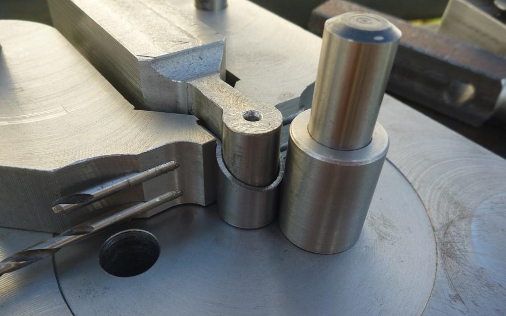
This is the next part of the Ross project, need to devise a way to form the socket required for the nose cap (would be open to suggestions on this)
What I had been contemplating is some kind of expanding mandrel and a clamp for forming the outside? which ever way there'll be a lot of machining regardless.
 WANTED: D1 - 8" Camlock either on a backing plate, or drive plate
DECENT CONDITION, REQUIRED FOR A PROJECT - SEND ME A PM IF YOUR ABLE TO HELP
-
21st February 2015, 08:14 PM #11
Philomath in training
- Join Date
- Oct 2011
- Location
- Adelaide
- Age
- 59
- Posts
- 3,149
Funny how things come together...
There was recently a thread that mentioned hydroforming and when I looked it up, I discovered "tube hydroforming" for example: http://www.inoxveneta.eu/cms/tube-hydroforming - basically make up a mould of the shape needed, insert a tube that has been stopped (possibly a welded plate) at one end and a pressure fitting at the other, pressurise the pipe and it expands to the required shape. (The link is for a production process, so does not weld up the end of the tube.)
Then there was another thread https://www.woodworkforums.com/f65/hydroforming-192560 which showed a video of someone using a pressure washer to do basic hydro forming.
In your case, two sides of a mould that bolt together and you would just have to trim the part to length. Use a high pressure pump and it should be easy.
Michael
-
20th June 2015, 02:10 PM #12
Senior Member
- Join Date
- Jul 2007
- Location
- Narnia
- Posts
- 113
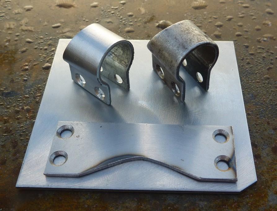
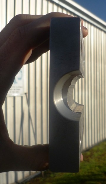
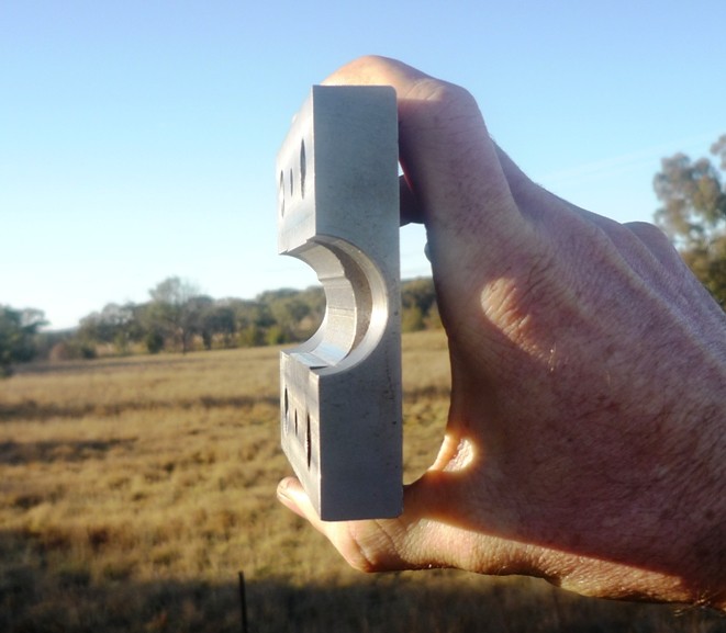
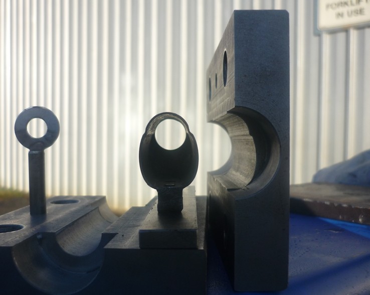
Hi All, my latest progress toward nosecap forming dies fresh off the mill. Massive thanks to MG for the inclination, tube hydro forming was not something i'd considered up until that point. Now need to get "keen" and cut that profile into the other half.
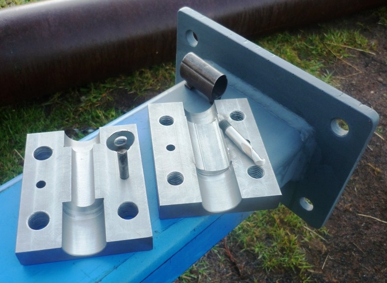
Have also sent the replica bayonet lug that I machined away for quotation. Firstly it went to a foundry but the componet size and detail was unsuitable (as i'd suspected) and they've referred it on to a business with cnc milling equipment, that specialise in small runs & prototyping etc.WANTED: D1 - 8" Camlock either on a backing plate, or drive plate
DECENT CONDITION, REQUIRED FOR A PROJECT - SEND ME A PM IF YOUR ABLE TO HELP
-
20th June 2015, 09:13 PM #13
Philomath in training
- Join Date
- Oct 2011
- Location
- Adelaide
- Age
- 59
- Posts
- 3,149
Originally Posted by BrianLara400*
 After that very kind wrap, I just hope it works!
(It should, but I've never done it personally, so I don't know the ins and outs of the process)
Michael


Similar Threads
-
1905 Toy Plans - Early Car
By chrrris in forum TOY MAKINGReplies: 6Last Post: 2nd December 2021, 05:12 PM -
Salvaged Teak From Deck Of SS Maheno 1905
By SpiritFlutes in forum TIMBERReplies: 4Last Post: 16th June 2012, 11:37 PM -
Just saying hi from Ross.
By rosscopeco in forum G'day mate - THE WELCOME WAGON -Introduce yourselfReplies: 3Last Post: 3rd May 2012, 05:57 PM -
Huon Pine Book Case made by my Great, Great, Great Grandfather
By Phil Spencer in forum WOODWORK PICSReplies: 19Last Post: 22nd November 2011, 09:31 AM -
Sailboat - GREAT project OR optional Granny flat
By SimonP in forum CLASSIC BOAT RESCUE & ADOPTIONReplies: 0Last Post: 30th April 2010, 01:29 AM
