

 Thanks: 0
 Likes: 0
 Needs Pictures: 0
 Picture(s) thanks: 0
Results 1 to 8 of 8
-
30th November 2014, 02:44 PM #1
 Senior Member


- Join Date
- Mar 2009
- Location
- Brisbane
- Posts
- 356
 Resistive Load for PSUs and Batteries
Resistive Load for PSUs and Batteries
I needed a resistive load to load up a 12 volt system to chase voltage drops in cables, connectors, earth runs, battery capacity testing, PSU loadup, and for other uses.
I always wanted to make one of these.
The requirement was to have current draw of 2.5/5.0/10.0/20.0 amps at 12 volts, and to be cheap and robust.
It should be able to draw up to 10 amps all day, and 20.0 amps for about an hour, before heat becomes a problem.
I used Whites Products 1.6mm 304 stainless steel "Garden Tie Wire" as the resistive element, available ex Bunnings for $13 for 15 metres. It is quite resistive, able to handle high currents, and relatively corrosion free.
This wire tested (over 5 metres) at approx 0.445 ohm per metre, and the measured diameter was 1.57mm.
I used a scrap piece of 8mm fibre cement paneling, 400 x 150 mm as the base, (free from Bunnings as it was a packing piece for FC sheet), and found some scrap aluminium angle as strengthening pieces.
I painted the FC base with Cabots water based clear PU paint.
I wound three windings of 19 and 9 and 9 turns, after doing the mathematics for the electrical length around the FC base, to give 2.4 and 1.2 and 1.2 ohms.
For 12 volts, all turns in series draws 2.5 amps, 19 turns draws 5 amps, 9 turns draws 10 amps, and the two 9 turn windings in parallel draw 20 amps.
These windings didnt need to be exact for me, but turned out quite accurate and within 5%.
Caution on the wire resistance, as the product wire material will vary from time to time, and yours might be slightly different. Measure your wire resistance before making up a unit.
You could use steel tie wire, but you will need much longer lengths.
My wire was only very, very slightly magnetic, even with a strong rare earth magnet (less magnetic than normal 304), so I dont know what exact type of SS it is, but it doesnt matter for this application.
After all, it is garden variety!!!
My device is prototype no 1.
Not really a thing of beauty, but works well and is sturdy.
If I make another one, I would make the FC base notches at ¼ inch spacing instead of 5mm, as in mine.
If you add a 12 V muffin fan, you could probably run the load at 20 amps all day.
cheerio, mike
P1150662lo.jpgP1150663lo.jpg
-
30th November 2014 02:44 PM # ADSGoogle Adsense Advertisement
- Join Date
- Always
- Location
- Advertising world
- Posts
- Many
-
30th November 2014, 02:55 PM #2
.
- Join Date
- Feb 2006
- Location
- Perth
- Posts
- 27,794
Looks pretty good to me. Originally Posted by mike48

Did you have to take the heating effect on resistance into account?
-
30th November 2014, 05:01 PM #3
Saw dust maker!
- Join Date
- Sep 2006
- Location
- Wandong
- Age
- 60
- Posts
- 453
It's a thing of beauty Mike... I like the fact you've taken a product meant for something completely different, and turned it into this!
I'm thinking an e-mail to the wire manufacturers with a picture and a good hearty recommendation for their products would leave them scratching their heads for a while
As a crazy suggestion, I wonder how it would go suspended in a (steel construction and insulated from the walls of course) bucket of water to keep the heat down? It seems no different to the old 'Birko' jug elements of a few years ago and I doubt the water resistance would alter the current draw too much... Of course, you'll be set for a well earned cuppa with freshly boiled water when the day is done
-
30th November 2014, 06:06 PM #4
.
- Join Date
- Feb 2006
- Location
- Perth
- Posts
- 27,794
Not a good idea as being DC this will electrolyse the water and corrode the wire. Originally Posted by Malibu
-
30th November 2014, 06:26 PM #5
Senior Member
- Join Date
- Mar 2009
- Location
- Brisbane
- Posts
- 356
Hi Bob
it will definitely be affected by temperature, but as it is not a calibrated device per se, it wont affect its function.
As I recall, the Temperature Coefficient of Resistance of SS304 is quite a bit higher than standard resistor materials.
It is positive, ie resistance increases with temperature, and approximates 8% from 25 deg C to 125 deg C.
It gets more interesting.
I think I can remember I read somewhere that as the temperature goes over about 500-600 deg C, the resistivity increase of SS304 starts to reverse as the ferrous state of the material undergoes molecular change.
I will have to read it up again.
If I get time through the week I will bench test and measure my load for the Rchange from 25-125 deg C.
I also use SS304 in rod and sheet form for high current shunts and it works well, but accuracy suffers as the temperature rises above calibration temperature.
This is why you need physically large shunts, ie to dissipate the generated heat, to offset the temperature rise
In most practical cases in cars and low voltage distribution, a measurement accuracy of 5% is fine as we are normally looking for approximation and trend.
I mostly calibrate my home-made stuff to 2% at 25 deg, ie workshop temperature.
Hi John,
the water idea is fine short term for 12 volts, and I have used water to cool resistors.
Mineral and vegie oil is better, but ...,
It all tends to be a bit messy, and you have to keep the hot load insulated from a steel can, or away from plastics!
In the old days before cheap high current diodes, we used to use to charge batteries at 10 amps using 400mA diodes in a bucket of water.
Failure rate was high.
No FMECA required here.
cheerio, mike
-
30th November 2014, 07:44 PM #6
SENIOR MEMBER
- Join Date
- Sep 2014
- Location
- Australia
- Posts
- 660
Great minds think alike! That was the first thing that sprung to mind for me! Originally Posted by BobL
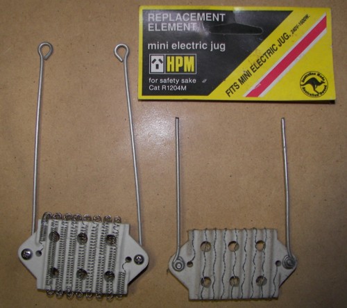
I used to make dummy loads the same way. I guess I am spoiled these days as I have lots of fancy test gear from when I used to design power supplies and battery chargers. But one of my favourite devices for making dummy loads was the old electric kettle elements. A nice wirewound resistor on a ceramic core! I doubt you could even buy them these days. They looked like this
-
5th December 2014, 02:40 PM #7
Senior Member
- Join Date
- Mar 2009
- Location
- Brisbane
- Posts
- 356
Did some bench tests today.
At 26 deg C the 19 turn section measures 2.41 ohm, and draws about 4.98 amp at 12V.
At 126 deg C it measures 2.53 ohm, and draws about 4.74 amp at 12V.
(I put in it our kitchen oven for 20 mins at 126 deg C; it smelled "well done").
This is about +4.97 % over a 100 deg C increase, or +4.96 x 10 E-4 ohms per deg.
These results mean the load function is affected by temperature, but the effect can be ignored in practice.
(Please make your own conclusions about "Measurement Uncertainties" in all the above).
Readers not rolling eyes upwards, and needing even more self flagellation can read -
http://www.dtic.mil/cgi-bin/GetTRDoc...f&AD=ADA129160
Note that SS304 has interesting high temperature TCR responses.
cheerio, mike
-
5th December 2014, 11:05 PM #8
SENIOR MEMBER
- Join Date
- Sep 2014
- Location
- Australia
- Posts
- 660
I would not be unhappy with that, i fact I would be pretty happy with it. That sort of error for a passive wirewound load is excellent IMO. Originally Posted by mike48


 Reply With Quote
Similar Threads
-
Batteries
By cookie48 in forum HAND TOOLS - POWEREDReplies: 17Last Post: 15th March 2011, 05:45 PM -
batteries
By peter mikk in forum FESTOOL FORUMReplies: 0Last Post: 15th June 2006, 09:05 PM -
batteries
By Miltzy in forum WOODIES JOKESReplies: 0Last Post: 20th May 2006, 11:09 AM -
Batteries.
By RETIRED in forum HAND TOOLS - POWEREDReplies: 4Last Post: 6th November 2000, 05:34 PM
