

 Thanks:
  Likes:
  Needs Pictures:
  Picture(s) thanks:
Results 1 to 15 of 38
Thread: Another HYCO SCROLL SAW thread
-
7th September 2015, 01:56 PM #1
 GOLD MEMBER


- Join Date
- Jan 2009
- Location
- Australia
- Posts
- 1,222
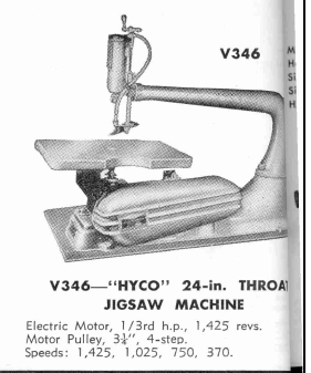
 Another HYCO SCROLL SAW thread
I found this at a recycling place out in Nelson Bay.
It was destined for scrap metal. I saw it there a few weeks ago but couldn't get close to see what condition it was in.
Dithered for a week then rang them and asked for it to be held for me. Luckily I did that as the bloke said it was going to scrap metal the next day.
Anyway. This is it on the floor.
Date? no data plate, so I am guessing mid 1950s. Has an electric motor, single phase 1/3 horse power. Made by HOOVER electricl in the UK! The motor plug was cut off as per normal. (But when I got it home I sneakily put one on and fired it up. I had checked for shorts and insulation and earth, first and that bearings were free) It ran just like a bought one.
The gearbox was filthy with years od wooddust mixed in with the oil. Took ages to clean out.
There is hardly any rust and that is on the table and is just surface, no pitting.
Paint has multiple layers of green, blue/grey and some blue hammertone?. But I think I will focus on running, not cosmetics and leave the paint as is.
I have four issues to contend with.
1. The electric motor pulley has a broken outer shoulder, I think as a result of the pulleys not being aligned (motor to gearbox) four good bolts will fix that.
2. The gearbox pulley has a stripped thread where the domed headed nut sits. But I think I can overcome that easily.
3. I am missing the hold-down footplate and blade guide. But I am hopefull someone will have photos dimensions and how to make suggestions.
4. The spring tension acme threaded winder is bent slightly, it is stoppinf the adjuster stop drom screwing down. I am hopefully going to straighten it without breaking it. Can you still get acme threaded rods to make a new one???
I will post up some of the photos I took during the pull down and clean.
Comments and suggestions as always appreaciated.
Attachment 358867Attachment 358868Attachment 358869Attachment 358870Attachment 358871Attachment 358872
-
7th September 2015 01:56 PM # ADSGoogle Adsense Advertisement
- Join Date
- Always
- Location
- Advertising world
- Posts
- Many
-
7th September 2015, 02:48 PM #2
 Senior Member
- Join Date
- Nov 2012
- Location
- Sydney
- Posts
- 266
Hi Lyle
Congratulations on picking up your new saw. I'm sure I can help with a few of your queries. I'll take a look at my saw tonight
Regards,
John
-
7th September 2015, 07:00 PM #3
GOLD MEMBER
- Join Date
- Dec 2007
- Location
- Melbourne
- Posts
- 3,277
I have got the exact same saw and of the same model/year. The early Hyco's had the cast belt covers and after they sold to Woodfast or sometime in between they went to a sheet metal cover.
The threaded rod on mine was bet also and I gently straightened it. Mine is a regular thread not an acme thread though???? The blue green hammertone is the original paint. I'm missing that whole foot and air tube assembly as well as the top blade clamp. I have just been pottering around on it in the shed and come in to see this.
Here is a complete one.
1955 Catalog
New Improved blade holders
See https://www.woodworkforums.com/f299/age-hyco-bandsaw-197436
Head Assembly from this thread
https://www.woodworkforums.com/showth...31#post1713731
Any details and measurements for the foot assembly would be appreciated so i can make something up for mine.�..Live a Quiet Life & Work with your Hands
-
7th September 2015, 07:12 PM #4
GOLD MEMBER
- Join Date
- Dec 2007
- Location
- Melbourne
- Posts
- 3,277
Forgot to mention mine has a � Hp 1440 3Ph motor. I'm going to try and fit a suitably old 1ph equivalent.
Also you will note that there cut out on the table can't be used without removing the belt guard and bracket.�..Live a Quiet Life & Work with your Hands
-
7th September 2015, 09:56 PM #5
SENIOR MEMBER
- Join Date
- Nov 2011
- Location
- Newcastle NSW
- Posts
- 775
Lyle,
Looks to be in good shape, sorry I couldn't make it Saturday. How bent is the spring tensioning threaded rod? Perhaps if you could put up some photos of the bent threaded rod?
This is a link to a post I did a while back fairly sure you said you had read it when we talked, but just in case here is a link
https://www.woodworkforums.com/showth...31#post1713731
I have outlined the parts that I saw when I pulled my head apart, I posted the picture recently on another thread, but this is it again (the numbers are outlined in the post).
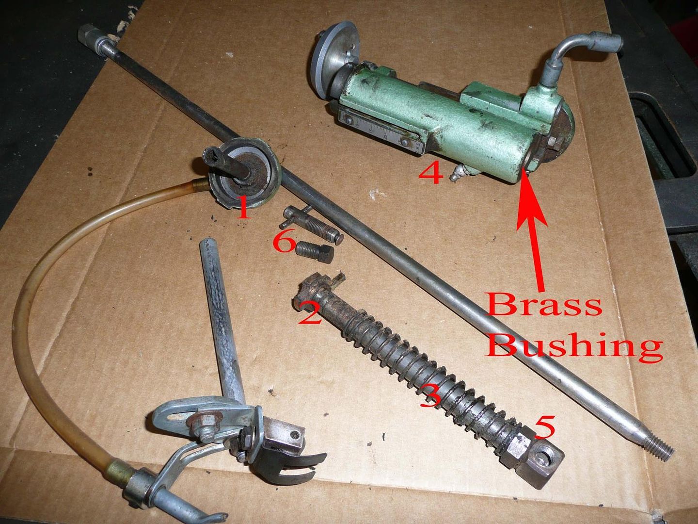
There is also some copies of leaflets that many were kind enough to post, Scott (Woodlens), was kind enough to send me this copy, worth a read.
https://www.woodworkforums.com/attachment.php?attachmentid=250292&d=1358566557
Something interesting was the description of the relief in the table on the pulley side, a good idea, I could imagine the pulley cover might get in the way on some of the other versions of these machines (when changing the blade).
I can measure my foot if it helps, but I think mine may actually have been remade, so hopefully John can help with this, I will be interested to see what his looks like. Glad to hear you cleaned out the oil (well oil sawdust mixture ), have you managed to get some SAE 50 oil, if your struggling to find some let me know.
Cheers,
Camo
-
8th September 2015, 10:22 AM #6
Senior Member
- Join Date
- Nov 2012
- Location
- Sydney
- Posts
- 266
Foot Assembly
Here's some dimensions for the foot assembly to get you started.
Foot Assy.jpg
1) Roller and Washer = 5/8"diameter x 0.46" long (total). The roller has 3 grooves to fit different blade widths (too narrow for me to measure), and sits beside a washer of the same diameter.Ideally the roller and washer would be hardened steel.
2) Screw pin (steel). Not sure of the exact thread size, but about 3/16" diameter, with slotted head.
3) Roller bracket (steel). 1" wide x 1/2" thick, cut at an angle such that the length at the top surface is 0.92" and 0.81" at the bottom. The roller is located such that the diameter of the roller just meets the corners when viewed from the side. The roller sits in a slot 1/2"wide.
4) T bracket is made from 3/16" thick steel bent from flat. The top of the T is 1-1/2" long. All sections are 3/4" wide, and overall length of the piece (estimated when flat prior to bending) is 3". The slots are cut to fit 1/4" bolts.
5) Spring foot is made from 0.7mm spring steel, and is clamped between the roller bracket and T bracket with a 1/4" bolt. Its fork is 1-1/4" wide and the opening between the leaves 1/2" wide and 0.825"deep. It is 1-1/2" long from the bottom of the roller mounting block to its tips, and chamfered down to 0.825" in width where it is clamped between the roller bracket and T bracket.
This should get you started
Regards,
John
-
8th September 2015, 01:47 PM #7
GOLD MEMBER
- Join Date
- Jan 2009
- Location
- Australia
- Posts
- 1,222
Thanks for the replies gentlemen.
A few photos of the process so far.
Attachment 358961Attachment 358962Attachment 358963Attachment 358964Attachment 358965
after pulling this apart I still don't know how this works, if at all, or if anything is missing. I can see a different construct to the photos posted previously, but those photos were of a wolfden? weren't they, so maybe a different construction. mine also has a bit of wear on the "cap tube".
Attachment 358969Attachment 358968Attachment 358967Attachment 358966Attachment 358970
The old electric motor is a 'HOOVER" made in the UK, and still goes OK. It has had a clean up and test. I am getting the old bearings replaced with sealed bearings and the grease nipples will be redundant. But it will still look original. The drive pulley is damaged, I suspect from the pulley misalignment in the photo.
Attachment 358973Attachment 358972Attachment 358971Attachment 358974Attachment 358974
To say the gearbox needed a clean out is an understatement. (gearbox cover inserted twice- oops). My blade holders had crush washers fitted between them and the holder posts is that normal or required? There were a heap of broken blade tips inside the bottom holder post along with a heap of sawdust. I am thinking of a bit of foam rubber inside to stop them falling into it.
I think the easy bits have been done, now the harder parts to replace missing bits will be happening.
Thanks for the posts.
I'll revisit the previous posts and ask questions or reply to them.
Lyle.
-
8th September 2015, 06:46 PM #8
SENIOR MEMBER
- Join Date
- Nov 2011
- Location
- Newcastle NSW
- Posts
- 775
Lyle,
I am taking a quick break from something, so I will have to make this brief. I just wanted to give you a rundown on how it works, so you can assess the parts. My machine is a Hafco, not Wolfenden (that's another great Australian company), but here are your images with some numbers on them, so I can go through the process for you
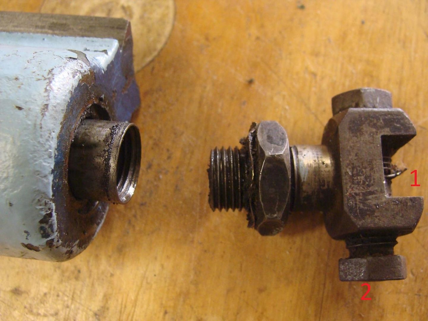
So when assembled, you would put your blade in between the bolts (1), and tighten one of the bolts (2), not sure if yours is the same as mine, but my one has a hole in the centre of the bolt to accept pinned blades as well as unpinned blades, and the tip of the bolt has a piece which can rotate freely, so as not to twist the blade at the final stage of tightening.
The other end of the blade obviously goes between the other bolts below the table. You then turn the pulley so the bottom section is at top dead centre, and apply pressure to the blade by turning the tension adjustment handle. If you do not bring the bottom shaft up to top dead centre, when you start the machine, there is a chance there will be insufficient tension at the top of the stroke and the blade will flex and whip, this will likely break the blade.
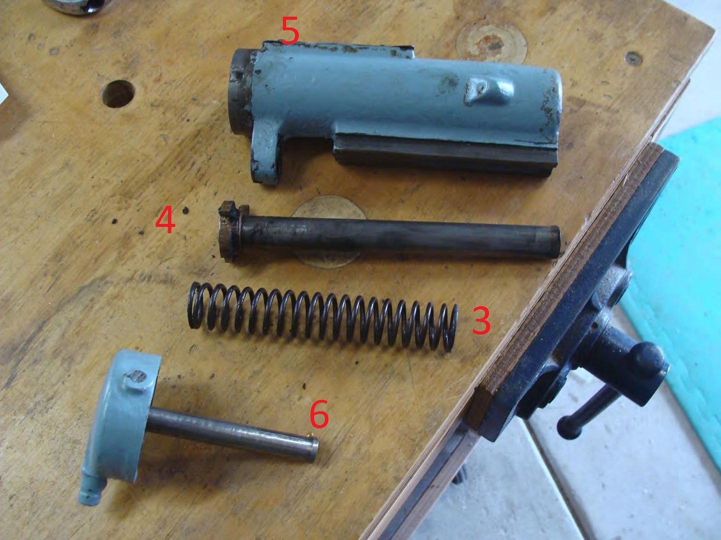
When you adjust the tension the inner shaft (4) wants to pull down as it is held by the blade, the spring (3) applies pressure against the shaft (4) and the brass lip at the top of the inner shaft (4) prevents it from rotating in the housing (5), as you wind the tension handle further, the spring is compressed and the brass lip moves down the housing, displaying the tension that is on the blade. The recommended tension was in the manual Steve supplied me, and I posted in my last thread (this is obviously just a guide as the spring will change over time).
If you have done everything correct, you will start the machine, the bottom shaft will move up and down, pulling the blade, the blade will move with this motion, and the spring (3) will apply enough pressure to keep the blade straight through the stroke without snapping the blade.
If you look at the bottom of (6) you will see a small lip, this seats inside (4), I believe their would have originally been an O ring or piece of leather, to form a partial seal. As (4) is drawn up and down with the stroke, this pushes a small amount of air through the tube in (6), which comes out on of the side outlet. This outlet had a tube leading down to the pressure foot assemble. The air is only meant to blow the sawdust enough to enable you to see the cut.
I have yet to fix my air blower, and to be honest, I may never do it.
Hope that's helpful, got to get back to what I was doing (I rushed through the explanation, so if something doesn't make sense ask, as I may have used the wrong number in my explanation).
Cheers,
Camo
-
8th September 2015, 10:34 PM #9
Member
- Join Date
- Aug 2012
- Location
- Brisbane
- Posts
- 96
Lyle,
You might be in luck. I ended up with two seperate hyco scroll saws.
Long story short, I bought the first one with plans to restore it, until it was moved which broke the body in half. What I noticed was that the saw rested on an original stand, however, the stand wasn't completely flat and had a concave in the middle, and when the saw was bolted down hard at both opposing ends + the vibration from moving the machine, caused a break straight accross the middle section of the casting. I assume years of pressure and tension built up. Basically, be careful of how it is bolted down and ensure a completely flat surface.
So that ordeal left me with a few parts I've been donating to others restoring a Hyco. Attached are a few photos of the parts I have left. Let me know if you would like any.
Also, as part of the original restoration, I bought a single phase motor. The second Hyco came with an original motor so it wasn't needed. If anyone is interested, let me know.
In the background of the last few pictures is my second Hyco. A real little Australian gem.
Regards,
Raymond.J.B
image.jpgimage.jpgimage.jpgimage.jpgimage.jpghyco.jpg
-
8th September 2015, 10:42 PM #10
GOLD MEMBER
- Join Date
- Dec 2007
- Location
- Melbourne
- Posts
- 3,277
Kif Lyle isn't interested, I am in the bits in the last two photos.
�..Live a Quiet Life & Work with your Hands
-
9th September 2015, 07:37 AM #11
GOLD MEMBER
- Join Date
- Jan 2009
- Location
- Australia
- Posts
- 1,222
Yes thank you very much. I'd like the hold down assembly and the blade tensioner/air blower assembly .
I will pm you with my number or get yours to call you.
I have a son in Bris who could.collect and bring down to here for me.
Thanks for the offer it is appreciated.
Sad to hear of your machine breaking. Too many old machines dissappearing.
Lyle.
-
9th September 2015, 08:42 AM #12
GOLD MEMBER
- Join Date
- Jan 2009
- Location
- Australia
- Posts
- 1,222
Thanks Raymond, a pm has been sent.
Lyle.
-
9th September 2015, 09:32 AM #13
GOLD MEMBER
- Join Date
- Jan 2009
- Location
- Australia
- Posts
- 1,222
Thanks for your reply Cameron.
I got confused by your photo. My blade holder has bolts, not a T bolt as yours shows. My blade holder bolts do not have the hole for pinned blades but do have the round bit to rotate when gripping the blade. I was looking at your photos and didn't realise that the blade holder was still attached to the shaft.
So I am more confident now that my setup is complete at least.
Thanks too for the description of the air blower operation. Makes sense now. I see a hole inside the body in the bushes in there. Two bushes? Have you had them out? I am wondering if there may have been a seal between them for the air blower operation? I cannot see in there clearly nor take a photo.
Lyle.
-
9th September 2015, 12:51 PM #14
GOLD MEMBER
- Join Date
- Dec 2007
- Location
- Melbourne
- Posts
- 3,277
Since Llyle doesn't need seem to need the top blade holder, I'd still like to put my hand up for that.
�..Live a Quiet Life & Work with your Hands
-
9th September 2015, 12:59 PM #15
GOLD MEMBER
- Join Date
- Dec 2007
- Location
- Melbourne
- Posts
- 3,277
John, That should be helpful in making one. Yours is different to the one Camoz posted does it mount directly to the rod or is there a foot on the rod also? Originally Posted by jcge
 �..Live a Quiet Life & Work with your Hands

 Reply With Quote


Similar Threads
-
Scroll chuck thread
By surfdabbler in forum WOODTURNING - GENERALReplies: 11Last Post: 29th April 2014, 05:19 AM -
Hyco scroll saw
By ozhunter in forum SCROLLERS FORUMReplies: 0Last Post: 19th January 2013, 02:16 PM -
Hyco Scroll Saw
By ozhunter in forum GENERAL & SMALL MACHINERYReplies: 0Last Post: 19th January 2013, 02:15 PM
