

 Thanks: 0
 Likes: 0
 Needs Pictures: 0
 Picture(s) thanks: 0
Results 16 to 30 of 67
Thread: Finishing a Yellowtail
-
6th January 2009, 01:55 PM #16
 Senior Member


- Join Date
- Nov 2000
- Location
- NSW
- Age
- 68
- Posts
- 108

Some progress photos. I sanded back the keel fairing fillet this morning. The fillet went on with a 100mm radius round spatula (a shaped piece of metal)
I've seen this done using plastic on top - to give a one-step, smooth finish, but I didn't have any plastic, so I used a left-over piece of 100mm black pipe as a sanding mandrel. The hole made it a lot easier to use....
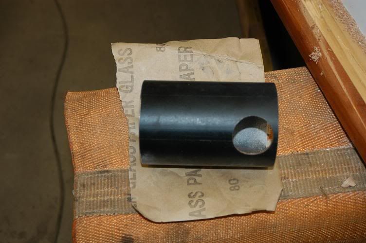
It only took 2 1/2 sheets of 80 grit and about 1/2 hour to get it right.

A quick touch up where there were some holes in the fillet.
I'll sand her back again tomorrow, ready for glassing the new keel.
-
6th January 2009 01:55 PM # ADSGoogle Adsense Advertisement
- Join Date
- Always
- Location
- Advertising world
- Age
- 2010
- Posts
- Many
-
7th January 2009, 06:37 PM #17
Deceased
- Join Date
- Dec 2007
- Location
- Guernsey Channel Islands UK
- Age
- 54
- Posts
- 307
that keel looks a lot better than the one see came with
 and it's good to see some one making progress on there yellowtail, i've come to a stand still on mine due to the freezing weather we have in the UK at the moment, i can cut some parts out but unable to epoxy anything
-
11th January 2009, 12:23 PM #18
Senior Member
- Join Date
- Nov 2000
- Location
- NSW
- Age
- 68
- Posts
- 108
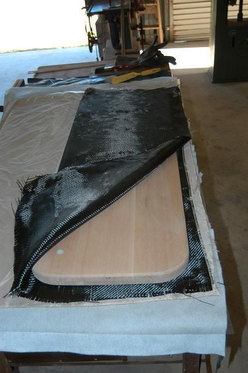
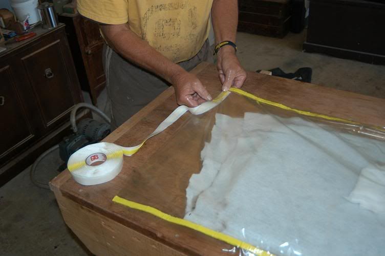
We sheathed the centreboard this morning Here she is, about 8:00am. Under the board is the Carbon, the peel ply and the breather fabric. The pivot point on the board has been drilled and filled with epoxy glue mix.
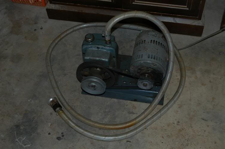
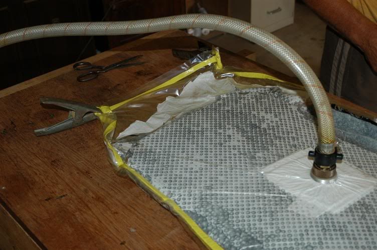
Here's Bazza's vacuum pump. It originally saw service producing television vacuum tubes.
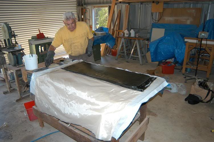
And, this is Barry putting the resin on.... I did manage to get plenty of resin on me too of course... I had to do the old plunging of the hands into sawdust trick before I picked the camera up a few times...
Both sides resined and stuffing the bag
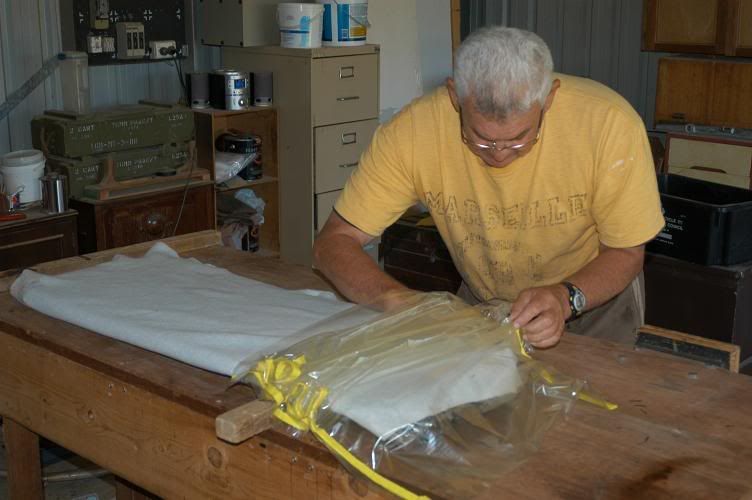
Sealing the bag with a bit of tacky tape..
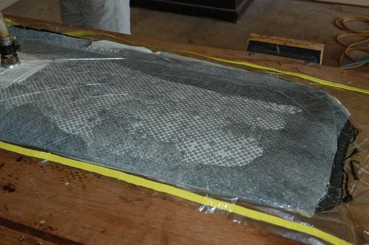
Vacuum applied and this was at about 8:45am....
....plenty of resin coming through the peel ply
.... and after a cup of coffee, the pump had grunted hard and sucked heaps through...
Given I've used carbon (195 gsm, 6oz) I will need to isolate any metal - carbon is right up at the top of the galvanic series table and will corrode any metal like crazy in salt water. The pivot point, as mentioned earlier is straight epoxy, and the lifting point will be isolated with a bush.
-
12th January 2009, 06:58 PM #19
Senior Member
- Join Date
- Nov 2000
- Location
- NSW
- Age
- 68
- Posts
- 108
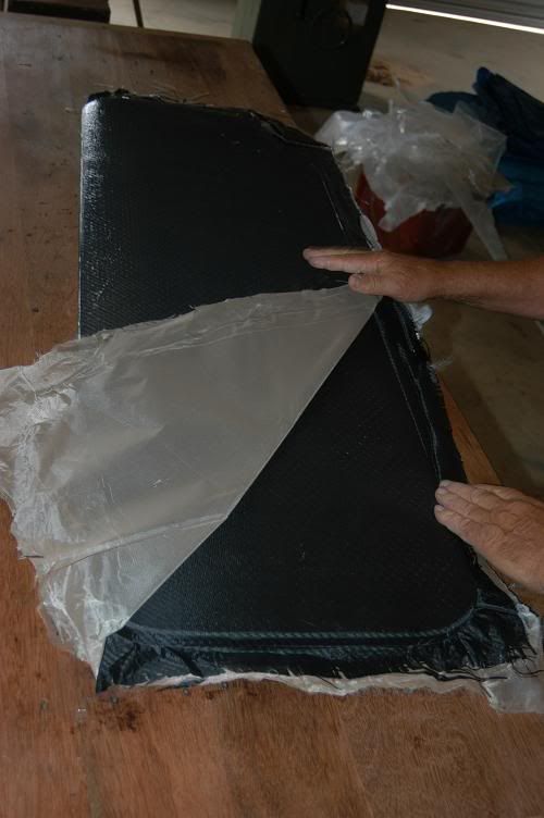
We pulled the board out of the bag this morning....
bag first,
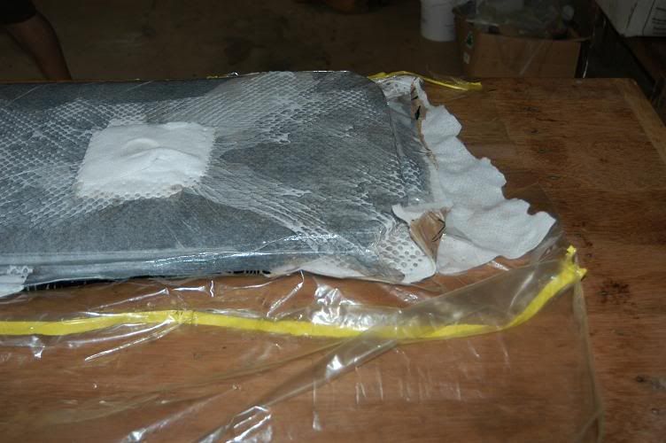
then breather,
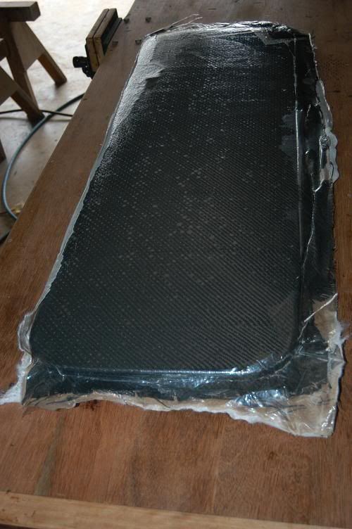
and finally the release film and the peel ply...
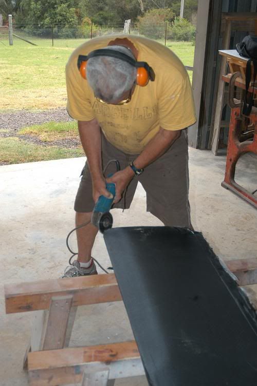
a quick trim by Barry with the diamond blade
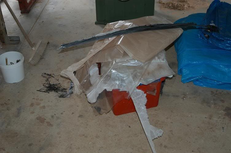
the obligatory pile of rubbish
then I brought it home for a quick (30 minutes) touch up with a bit of 80 grit - mainly to smooth the edges and a couple of very small resin ridges..
Since then I've cut back the carbon around the pivot point - and I'll cover that area with a bit of ordinary fibreglass, so that I avoid corrosion issues. The same will be done for the attachment point for lifting the board.
I weighed it today - 17.6 kg.
-
12th January 2009, 07:25 PM #20
GOLD MEMBER
- Join Date
- Mar 2007
- Location
- Adelaide
- Posts
- 2,139
Very interesting Mr. igatenby,
Nice, you blokes look like you know what you are doing
Have to ask the question: Why carbon it's looks great but have to wonder about the technical issues not to mension the degree of difficulty
Cheers
Mike
-
13th January 2009, 09:32 PM #21
Senior Member
- Join Date
- Nov 2000
- Location
- NSW
- Age
- 68
- Posts
- 108
No great degree of difficulty there - no more than if it was plain glass, obviously it helps having access to the vacuum pump though. The pressure applied to the board by the pump is amazing - the carbon layer is compressed to less than half a mm.
As for technical reasons. Not my province but I believe carbon is superior when it comes to compression loads - which is what you need on foils. It certainly makes the board feel different - flick it with a fingernail and it rings now.
edited to add - I wish the foils on my old Tornado, which I used to race 30 years ago were as nice as this one.....
-
2nd February 2009, 09:24 PM #22
Senior Member
- Join Date
- Nov 2000
- Location
- NSW
- Age
- 68
- Posts
- 108
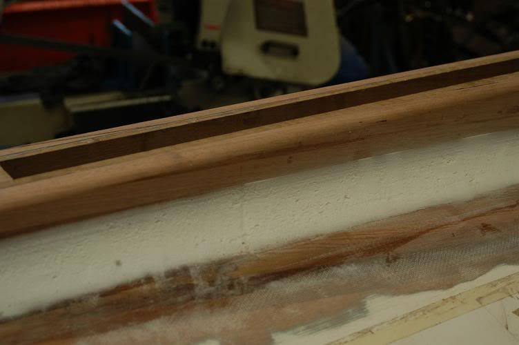
Time for an update. I've got the bronze bits in - thanks to Mike at Wooden Boat Fittings.
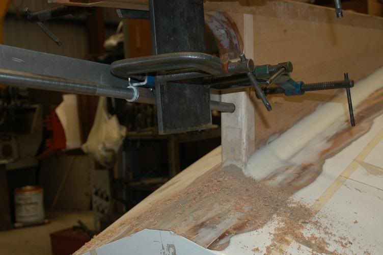
Yesterday was big hole-drilling day. We bored the hole for the shaft log.
Steve machined up a drill holder.
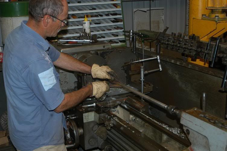
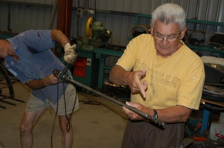
Here's Bazza doing the big demo. Its a 3/4" auger sunk into a hole in a 3/4" rod and held there by two grub screws. We had to skim a bit off the rod to let it go in smoother - 59 thou came off IIRC. That meant we had to bush our guide - but it didn't take long (the bush is visible soon)
Getting set up for angles - we'd lofted the angle when we made the keel of course - this was just a matter of clamping the straight edge to the pencil line on the keel.
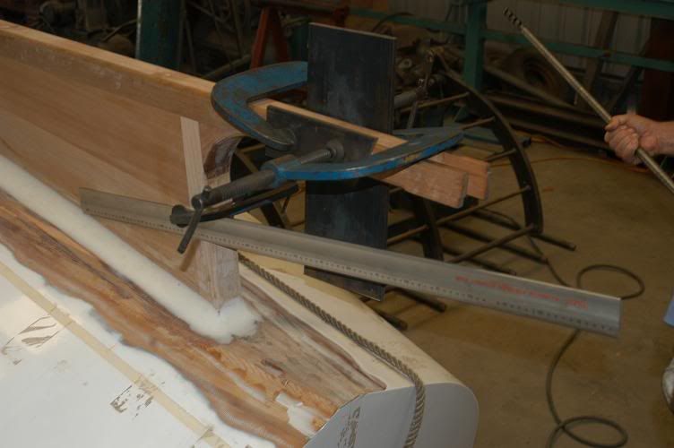
A couple of bits of tube, tacked to the square tube in the appropriate spot to get dead centre.... I think the bush is visible in the rear bit of tube here...
It certainly is here
-
2nd February 2009, 09:25 PM #23
Senior Member
- Join Date
- Nov 2000
- Location
- NSW
- Age
- 68
- Posts
- 108
Once the guide hole was done, Steve made the cutter. A new hole at 90 degrees to the grub screws, a bit of high speed steel in the hole, an attack with the angle grinder to give it a cutting edge, and Bob's yer uncle. We had to touch the edge up once on the way through - and knock out some accumulated shavings with a hammer and rod from the other end about four times. Not bad for a 600 mm or so hole.
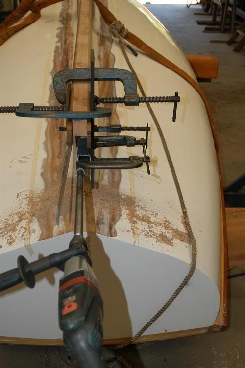
The nose of the rod provides a guide for the second cut btw. The rod is held in two spots for the first cut and three spots for the second. As Steve said - no moonbeams (lasers), no guessing....
Yep - we got it smoking on that shaving build up one time....
My job in all this was to provide the ballast. I got to lean on the bow while Steve drilled.
I'll run a sanding "mop" through it next, then epoxy it. I have to get some bronze tube and there's a bit more machining to do with it.
I forgot to mention - when we did the second cut - we did the first 2" in with the cutter set at 1 1/2" - then dropped back to 1 1/4". We (OK, Steve) will mill a length of 1 1/2" so the first 2" has a socket for the stern gland, then cut the rest down to 1 1/8" (maybe a tad more) by 1". The shaft will be 3/4".
__________________
-
2nd February 2009, 09:42 PM #24
Deceased
- Join Date
- Dec 2007
- Location
- Guernsey Channel Islands UK
- Age
- 54
- Posts
- 307
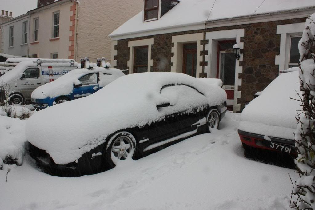
it's coming along nicely, mine is still on hold as this is what greeted me this morning
when will the weather warm up
-
2nd February 2009, 10:07 PM #25
Senior Member
- Join Date
- Nov 2000
- Location
- NSW
- Age
- 68
- Posts
- 108
Is that an Aston Martin under there? Just say yeah - and really P me off...
You want hot - its mid 30's here all this week and will be 42 on the weekend (108F).
-
2nd February 2009, 10:27 PM #26
Deceased
- Join Date
- Dec 2007
- Location
- Guernsey Channel Islands UK
- Age
- 54
- Posts
- 307
i wish i could P you off by saying it is an Aston Martin but it's my Nissan R33 Skyine Originally Posted by igatenby

we should do some sort of trade i'll send you some snow and you can send me some sun (it's blommin freezing in the part of the world)
-
2nd February 2009, 11:34 PM #27
Senior Member
- Join Date
- Nov 2000
- Location
- NSW
- Age
- 68
- Posts
- 108
I believe you can have a bit of fun with the R33s. I've got an E34 M5 Bimmer up on blocks at the moment. Got a call from the wife a few weeks back "it went bang and it won't go any more". She tore the diff out of it. Truth be known, I tore the diff out on the track - it just happened to fall out when she was driving Originally Posted by honkongphoie
Repairs are all done, I just need some diff oil and have to reassemble the rear end pieces.. all the new bushes and bearings are in.. I need to get that done before I glass the new keel on the Yellowtail too.
-
26th February 2009, 11:46 PM #28
Senior Member
- Join Date
- Nov 2000
- Location
- NSW
- Age
- 68
- Posts
- 108
Well, the M5 is back on the road - with a nice tight rear end, just waiting for a couple of track days to abuse it some more.... and I've done some more to the Yellowtail
Since no-one asked the obvious question. Did drilling the shaft log work as intended? The answer was, yes, and no.
It was a pretty good result, but slightly off to one side, but the fix was easy ...
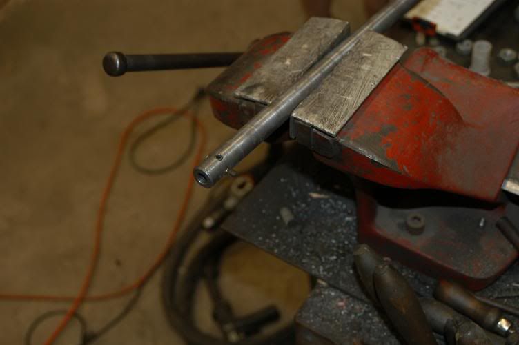
Weld it up, of course.... this is Steve with the Tig (yeah I've got one at home too - but he really knows what he's doing with his....)
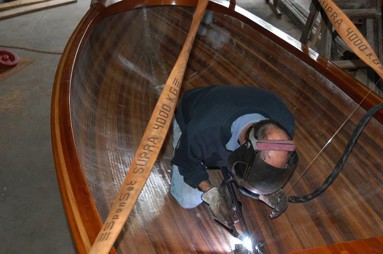
Steve welded up another little jig, so that we could come back from the other side as we opened the hole up to full size. I lashed out and bought another bit of steel (for once Steve didn't have a bit the right length...) So - a 22mm bright steel rod 1.3 metres long - just enough to do the job. Broke the bank... $14.30.
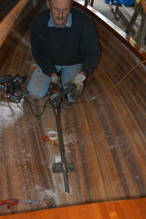
Steve whipped it down to fit the drill chuck, ran a hole through half way along for the cutter (same one from last go - just a bit of high speed steel rod shaped and with an edge put on with an angle grinder and a grub screw.
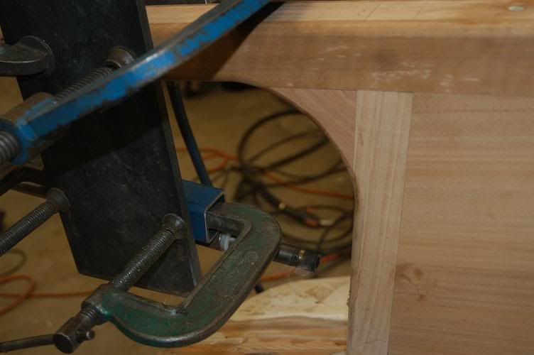
The reason for the new rod? We needed the cutter in the middle of the rod, so that we could pick up both guides (inside and outside the boat) at the same time. The jig was just a bit of pipe with a bit of clearance welded to a bit of angle iron - with a couple of slots to screw it to the keelson and allow adjustment. About 30 minutes to put together. Why the clearance? No oil or grease of course. I did pour in a bit of water at times to lubricate it. Didn't need much.
Steve drove the drill.
We finished it off with a sanding mop (flap wheel) in the original rod - which had the hole in the end of the rod. Nice neat hole.
I test fitted the bit of 32mm electrical conduit. We drilled to 35mm and I have fibreglass / epoxied the conduit to stiffen it up. We actually did that on the lathe - a bit of aluminium tube inside to keep it straight, some fibreglass tape, slow speed turn - along with the tape, brushed the epoxy on and left it turning until the epoxy dried - no nasty runs in the glue. A quick whip over the linisher and it fits in nicely.
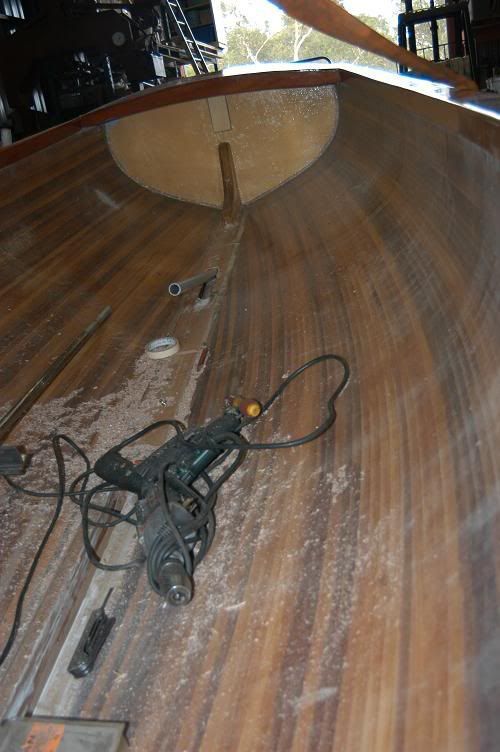
So, there it is - a nice little hole..... in the right spot.
The hole under the conduit in the keelson was hole for the original keel - which was just left out pieces of timber in the keel. No thank you. I'll fill it when I put a block around the inner part of the conduit...
I've also fibreglassed the new keel and inside the centreboard slot. It has a layer of 300gsm cloth followed by a layer of 200gsm. I haven't filled the weave yet, but did a few minutes today fiddling with the brass strips that are going on the bottom of the keel and up the stem. I'd have used bronze if I could have sourced it locally.... at least I've got silicon bronze screw to secure it. They will be set in epoxy plugs.
I'll be routering out the bottom of the keel around the slot to take some 3mm insertion rubber.
I've got two different width D moldings to do the stem - thin above the U bolt and thicker below - meeting up with a wide 5mm thick strip as far as the slot - then two narrower bits down the side of the slot (these will sit over the edge of the insertion rubber) and a wide one down the back. I've bent the D sections to shape today - its imperative to do this before drilling the holes (otherwise ..... snap).
I've filled the carbon fibre weave on the centreboard and set up the hole and lifting locations - including some plain glass laminations in these areas and epoxy plugs to isolate the metal from the carbon. Next step is to double check the board clearances with a temporary mount and lifting rope... Can't go further if she's too tight.
As soon as I get the brass strips on the keel, we'll finish off the trailer bunks and I'll bring her home for a fairing session or two and a bit of paint. Then its a bit of sorting out of the glassing job inside and the fitout. The glassing job on the inside has a few bubbles around the keelson. I'll cut it back and re-do it properly. It looks like he used a brush or something else that he shouldn't have to glass the insides. A 3" foam roller is the go.
So .... planning to move it along a bit next week.
Oh - nearly forgot. I've moved the engine along a bit too. The guy that did my head and honing work on the M5 engine when I rebuilt it did some work on the bronze Blaxland for me. He had to do it all by hand, as the bits were too small for his engine building machinery. He levelled up the bearing caps so that they sit flush and we have the right clearances and he linished the crank. I felt like a bit of a vandal when we put the bronze block under the drill press and whacked a couple of holes in to take greasers. As Steve said though, it would be vandalism to not do it. There was already a hole at one end - but it was full of new white metal from when Aub did the new bearings a couple of years back (its never been run since by the look of things). We drilled and tapped that same hole and put another in at the other end in the same spot as my other engine. I'm using the greasers off the other engine...
-
27th February 2009, 03:22 PM #29
GOLD MEMBER
- Join Date
- Mar 2007
- Location
- Adelaide
- Posts
- 2,139
Very cool Mr. Gatenby
-
25th March 2009, 08:06 PM #30
Senior Member
- Join Date
- Nov 2000
- Location
- NSW
- Age
- 68
- Posts
- 108
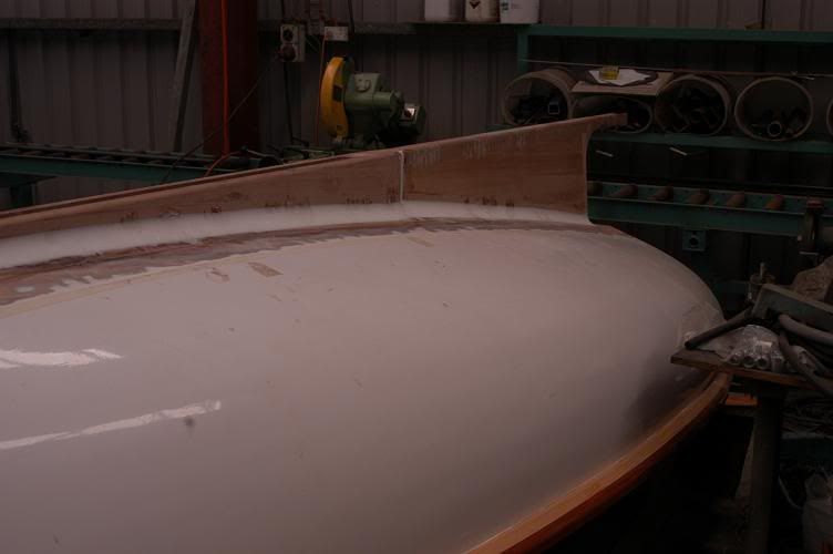
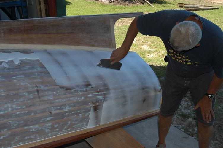
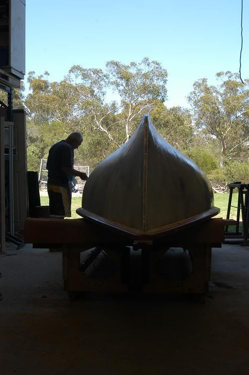
So .... I sanded her back - using electrical powered devices...
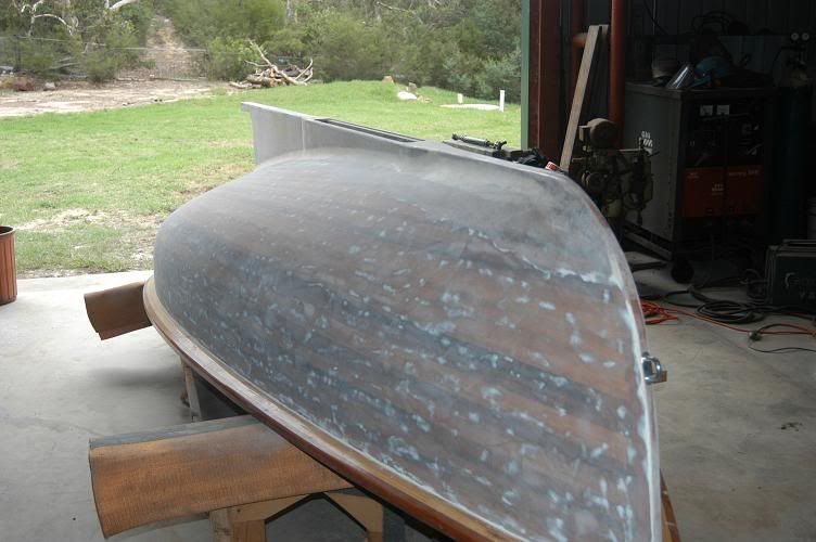
Then we gooped her up, with a gallon + of West System and microspheres...
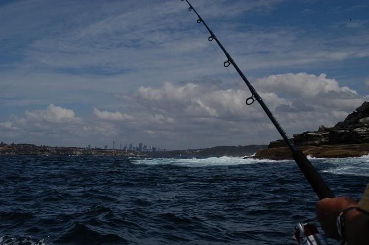
went fishing (caught a very nice kingfish) ....
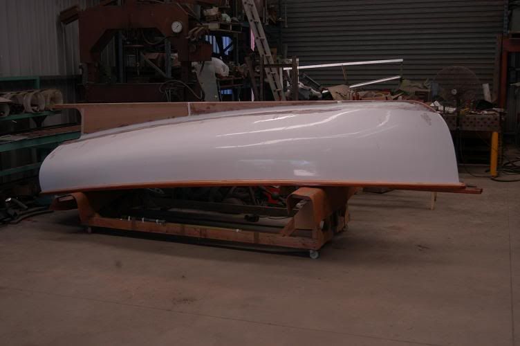
... I did about 25 hours longboarding... I really wish the hull builder had planed her a bit better before he sheathed her ... then we whacked her on the new trailer and I brought her home
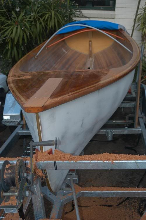
I planed the anchor handling gear off today - a lump of mahogany about 2" x 4" - I need a bowsprit where that was - and I need to organise the mast partners and finish the deck so that I can paint the hull. I've bought Sterling Lacquers products - high build epoxy primer and 2 pack polyurethane. I think I'll spray it (I have my own remote breathing gear - but will need to hire a booth).
Next job will be to get rid of the timber props under the gunwhales and organise some proper beds on the trailer.

 Reply With Quote
Similar Threads
-
another Yellowtail begins
By honkongphoie in forum BOAT BUILDING / REPAIRINGReplies: 88Last Post: 30th June 2009, 09:19 AM -
Woo Hoo got my yellowtail plan today
By honkongphoie in forum BOAT DESIGNS / PLANSReplies: 7Last Post: 9th August 2008, 10:10 PM -
Yellowtail Yawl Update
By Daddles in forum BOAT BUILDING / REPAIRINGReplies: 5Last Post: 26th July 2006, 12:07 PM -
Introducing, the Yellowtail Yawl
By Daddles in forum BOAT DESIGNS / PLANSReplies: 19Last Post: 16th June 2006, 06:31 PM -
Me Yellowtail
By Daddles in forum BOAT BUILDING / REPAIRINGReplies: 19Last Post: 26th March 2006, 05:04 PM
