

 Thanks: 0
 Likes: 0
 Needs Pictures: 0
 Picture(s) thanks: 0
Results 1 to 15 of 73
Thread: Coffin Smoother
-
13th October 2008, 09:35 PM #1
 GOLD MEMBER


- Join Date
- Jun 2008
- Location
- Victoria, Australia
- Age
- 74
- Posts
- 6,132
 Coffin Smoother
Rather than clutter Peter's how-to thread, I'll start a new thread for my blunders and mistakes.
The Hock blade arrived, so the design has changed to suit that. I got the brass sides cut out and filed, and made up a jig from pine to bend the brass to suit the curve, but it sprang back more than I thought it would. So I made a seperate jig just to over-bend slightly to allow for spring back.
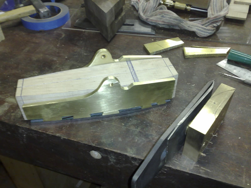
Next step is to cut the pins on the base. But I think I'll hold off until I see Peter's next installment.
In any case, I think the base is supposed to have a tongue and groove joint, but If I cut the pins at the front, I can't move the front plate after that... so I think I need to do the rough cut mouth opening and tongue & groove joint (plus the anti chatter block) before starting the pins...
What's the recommended sequence?
What is the benefit of having a tongue & groove to adjust the mouth opening if it can't be moved? (after dovetailing)
That block of brass on the right of the Hock Blade is going to be the lever cap.
Regards
RayLast edited by RayG; 13th October 2008 at 09:37 PM. Reason: re-formatted
-
13th October 2008 09:35 PM # ADSGoogle Adsense Advertisement
- Join Date
- Always
- Location
- Advertising world
- Age
- 2010
- Posts
- Many
-
13th October 2008, 11:00 PM #2
SENIOR MEMBER
- Join Date
- May 2007
- Location
- Melbourne
- Age
- 58
- Posts
- 832
Looking good Ray.
I'll watch with interest. Kevin
-
14th October 2008, 12:22 AM #3
Peter McBride
- Join Date
- Nov 2007
- Location
- Melbourne
- Posts
- 1,139
Ray, Originally Posted by RayG

Just love to see your plane moving along.!!
A few thoughts....
How much metal have you left extra to peen the dovetails into the base?
To lay out your pins you will need to do a bit of creative work with dividers and rule. And it will be a bit of a challenge getting the 6mm wide stuff over the pins on the curved sides. If I was to make a coffin side plane I would use the Spiers method, tails on the base and pins on the sides, so the sides are assembled down onto the base, not from the side as you have done. I would cut the tails on the base first and then mark the pins from that.
Be a little cautious about the location of the pivot hole in the lever. I drill the hole in the lever first then locate the hole in the side with the infill almost done and the blade and screw in the lever placed in the plane. If your drawings are good, and the blade set and lever thickness are true to your drawings you will be sweet.
I work from what I know...to what I don't know, so I don't lock in an element that might be changed a little later on if 2 or 3 more critical steps or dimensions or locations control it.
The T&G joint is there in bevel up planes so the 1mm wide throat can be made, and the adjustment you are referring to is probably in the making process....getting it adjusted to 1mm in the making.
Prep the blade seat, them rivet the block behind, and then finish file seat for the blade.
The throat doesn't have to have the T&G joint. It is about 6.5mm on a Norris 50G with a 47.5 deg. blade, and would be a bit less if the blade angle is higher. So you can fit a file through the opening.
Seen here.
If it is made in 2 pieces it is MUCH easier to get the blade seat right, but is a little more difficult to do the T&G joint. Your effort so far would indicate the T&G should be doable.
Here is a step by step...
Use the back of the throat as your datum line, and work all the dimensions from that line. ( it will be important for the position to correlate with the lever cap location because holes in the side are already there.)
Make the back piece of the sole first, ( you already got that) , cut and file your blade seat and leave the lugs about 3 or 4mm long on each side forward of that throat datum line. The front of the throat, if the opening is made to say 5.5 will be too narrow, but is easily filed wider with the blade located in the plane as a guide.
So from your datum line work out how long you need to leave the lugs that will form the other half of the T&G joint.
Once you have the sole connected with the T&G joint it is quite rigid.
Although you have spent some time on the tails, you might consider a change to pins on the sides and tails on the base. ????
Regards,
Peter
-
14th October 2008, 07:02 AM #4
GOLD MEMBER
- Join Date
- Jun 2008
- Location
- Victoria, Australia
- Age
- 74
- Posts
- 6,132
Hi Peter,
Very timely advice, I will follow your suggestion and go with pins on the sides. That 1/4" brass is heavy stuff...
I have allowed about 3/16 extra length on the brass for peening, which I hope is more than enough.
Thanks for the tip regarding the lever cap rod location, my layout has changed from the original I had owing to changing to the hock blade, so I need to re-draw everything.
It's all good fun!
Regards
Ray
-
16th October 2008, 12:39 AM #5
GOLD MEMBER
- Join Date
- Jun 2008
- Location
- Victoria, Australia
- Age
- 74
- Posts
- 6,132
After changing blades, EVERYTHING changes....
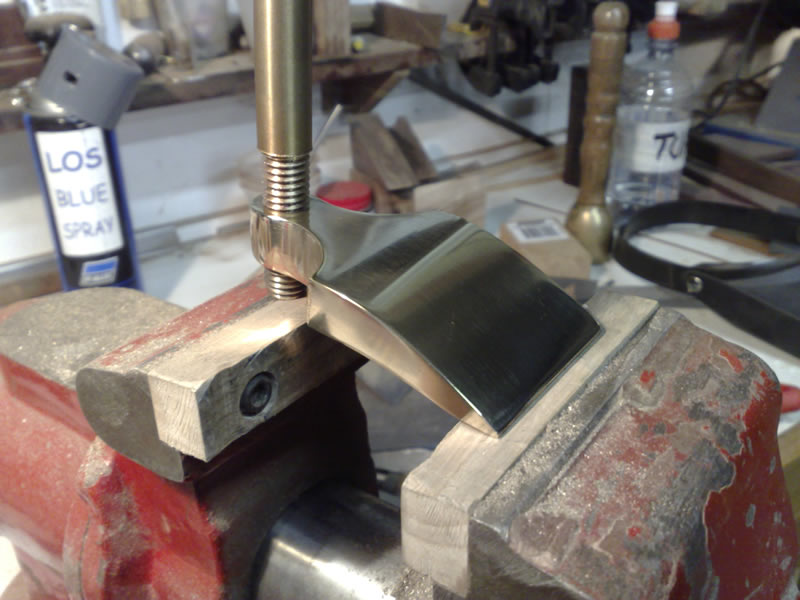
The geometery now looks like this, to see where the lever cap and screw will go
I had to do a bit of preliminary shaping and cut a bit of thread to see where the lever cap screw would end up against the blade assembly.
The thread is 1/2" 13 tpi it will be silver soldered into a 1" knurled cap.
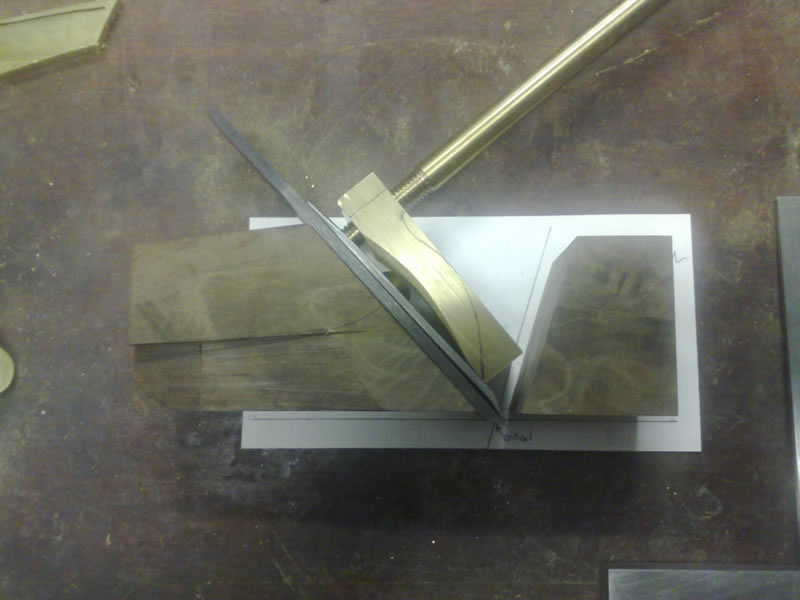
Now I know approximately where the mouth is going to be I can get back to work on the base...
Regards
Ray
-
16th October 2008, 09:14 AM #6
Peter McBride
- Join Date
- Nov 2007
- Location
- Melbourne
- Posts
- 1,139
Ray, Originally Posted by RayG
It may be the perspective in the picture, the gap between the lever and rear infill looks a little close. Don't snooker yourself by not leaving enough room to slide the thickest part of the blade set out between the lever and the rear infill. Most Norris planes don't have the brass domed nut on the back iron, so they can be a real close fit. Other makers filed the brass dome down much thinner than on a wooden plane blade set, but on some I have seen, the clearance is real tight.
Regards,
Peter
-
16th October 2008, 10:00 AM #7
.
- Join Date
- Feb 2006
- Location
- Perth
- Posts
- 27,790
Looks great Ray, thanks for posting.
-
16th October 2008, 10:32 AM #8
GOLD MEMBER
- Join Date
- Jun 2008
- Location
- Victoria, Australia
- Age
- 74
- Posts
- 6,132
Hi Peter, Originally Posted by lightwood
No, it's not perspective...(doh!) I need to lift the lever cap (maybe 1/8" higher) than shown.
Which in turn will move the pin location slightly... and to compensate for that the sides can come forward a touch... which changes ....
... Just as well you picked it up. (thanks)
Regards
Ray
-
16th October 2008, 10:35 PM #9
SENIOR MEMBER
- Join Date
- May 2007
- Location
- Melbourne
- Age
- 58
- Posts
- 832
Ray (&Peter),
you guys rock. It is great to see the banter and sharing of ideas in a very real, practical way. Thanks for sharing the build and design process.
Kevin
-
16th October 2008, 11:42 PM #10
GOLD MEMBER
- Join Date
- Mar 2005
- Location
- In the shed, Melbourne
- Age
- 52
- Posts
- 6,883
Oh goodie
 another beaut hand made plane thread to follow.
-
17th October 2008, 12:05 PM #11
GOLD MEMBER
- Join Date
- Jun 2008
- Location
- Victoria, Australia
- Age
- 74
- Posts
- 6,132
Hi Peter, Waldo, Bob, Kev, Derek,
While I see Peter's got the sexy job of filing the dovetails, I spent about 5 hours last night
filing a rectangular hole in a piece of mild steel. (surely I can't screw this up!)
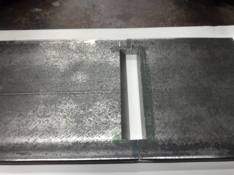
The advantages of the T&G joint suddenly became obvious, I imagine filing the bedding angle would be difficult. (bloody near impossible) with a narrow opening, and everything else in the way. With the T&G joint you have complete access and lot's of room to see what's happening. Then adjusting the other side for the mouth opening is just a matter of filing the grooves a little deeper with a few passes of the file. (to cut the grooves I found a file about the right thickness and made safe edges on top and bottom of the file and just used the edge to cut the groove. I finished up about 1mm too tight, which I hope will be enough to work with. I expect to loose a bit when the sole is lapped flat and then the final bit to determine the mouth opening will be after everything else is done.
I showed my wife ( maybe a little bit proud of my efforts, I suppose) she seemed singularly unimpressed with the amount of effort required to make a rectangular hole in a bit of scrap steel... (and as she pointed out, the sides aren't square) The discussion of traditional Spiers and Norris 47.5 degrees and 55 degree york pitch was going nowhere fast... Some people just don't get it.
Here is my setup for filing, (looks suspiciously like the saw filing setup, without the saw vise). I find that if you get the light reflecting off the surface as you are filing you can see exactly where you are and adjust the amount of pressure and such accordingly. The magnifier is handy but I didn't really use it for this job.
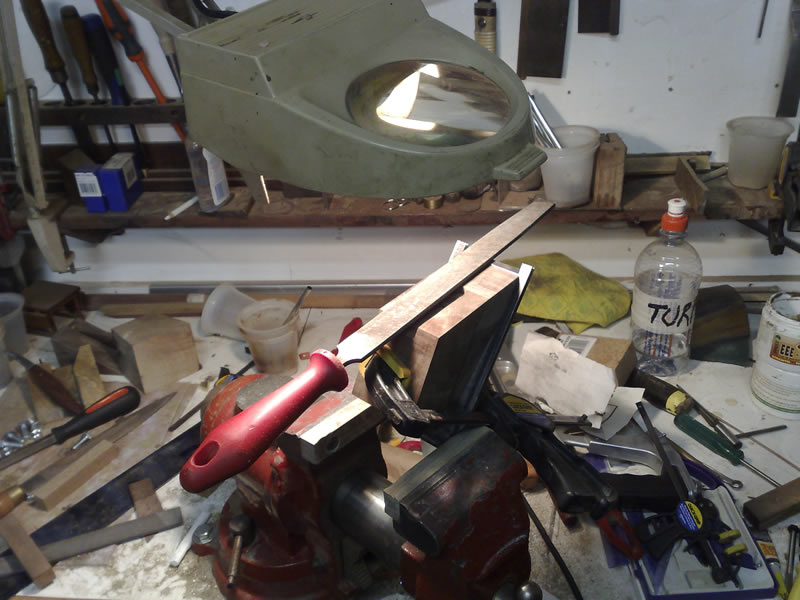
Next is the antichatter block...
Regards Ray
-
17th October 2008, 12:08 PM #12
GOLD MEMBER
- Join Date
- Mar 2005
- Location
- In the shed, Melbourne
- Age
- 52
- Posts
- 6,883
Wives never understand Originally Posted by RayG
 the attraction of all things timber/metal and the time we spend doing it.
-
17th October 2008, 01:28 PM #13
Peter McBride
- Join Date
- Nov 2007
- Location
- Melbourne
- Posts
- 1,139
Ray, Originally Posted by RayG
Great work!!
Isn't it a treat when the light globes light up above your head all the time doing this. There are just so many variables, and when you can wrangle them all together inside you head without it exploding, a certain calmness descends...tell me someone else finds this a bit mystical...oh heck... it's just good fun isn't it??
AND I'm very familiar with the little quizzical look....then the eyes glazing over when I try and explain the various benefits and penalties of different plane options.
That magnifier might be just the thing for when you do the final touch up to fit the sides to the base. I use a binocular viewer.
BTW...I'll do your T&G joints if you do my dovetails
Looking real good,
Regards,
Peter
-
17th October 2008, 02:10 PM #14
SENIOR MEMBER
- Join Date
- May 2007
- Location
- Melbourne
- Age
- 58
- Posts
- 832
OK,
now I'm getting itchy feet. I need some shed time, now. I'm feeling more like a lurker than a doer at the moment.
Its cracking on Ray and looking great. Thanks for the push.
Kevin
-
18th October 2008, 02:11 PM #15
GOLD MEMBER
- Join Date
- Jun 2008
- Location
- Victoria, Australia
- Age
- 74
- Posts
- 6,132
Hi Kev, Originally Posted by kevjed
Don't thank me, thank Peter for kicking off the inspiration, and Helmut (and Yourself) for the "Great Bulk Brass Buy of 2008". I was going to say it's easy, but actually there is a lot of complex interrelated factors that all have to come together, it's lucky we have Peter here willing to help out. The forum is perfect for this type of project, everyone can learn from my mistakes (!)...
Here is the the Lever Cap. I hacked away with files for a bit, then nibbled a bit more on the bandsaw, then smoothed a bit on the linisher, then back to the files.. pretty much whatever you have to hand to remove the non-lever cap bits.
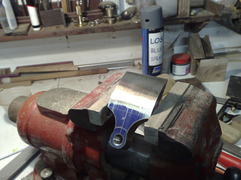
You might notice, I have gone "up-market" with a spray can of blue layout paint, seeing Peter's nice clear layout lines compared to my scratches over texta convinced me to lash out and buy the blue stuff, ... looks nice on brass too.
Once the shape was established, smoothed out the file marks with cabinet scrapers (worked a treat), sanded it down with 240/400/800 then off to the buffing wheel.
Now, looking at it and comparing the shape with others, I think I might re-work the neck to make a bit of a curved break.. it looks a bit plain.
The final tweaking of the bottom front (where it contacts the back iron) will be done later, and I'll hold off drilling the pin location until the body is done.
Regards
Ray
Edit: That photo shows the wooden vise jaws a bit a felt can be stuck on for further protection.


 Reply With Quote


Similar Threads
-
building a coffin smoother?
By zac_in_ak in forum HAND TOOLS - UNPOWEREDReplies: 12Last Post: 17th September 2008, 04:17 PM -
Coffin up a joke
By Allan at Wallan in forum WOODIES JOKESReplies: 7Last Post: 21st February 2008, 11:18 AM -
The Coffin
By fenderbelly in forum WOODIES JOKESReplies: 2Last Post: 24th October 2007, 07:29 PM -
Coffin splutter
By Allan at Wallan in forum WOODIES JOKESReplies: 2Last Post: 6th September 2007, 10:00 AM -
Coffin
By ozwinner in forum WOODWORK - GENERALReplies: 2Last Post: 17th October 2003, 04:23 PM
