

 Thanks: 0
 Likes: 0
 Needs Pictures: 0
 Picture(s) thanks: 0
Results 1 to 15 of 15
-
20th April 2008, 05:26 AM #1
 Be inspired. Be creative. Be bold.


- Join Date
- Apr 2001
- Location
- Perth
- Posts
- 10,831
 Cutting dovetails to cut dovetails
I would like some input here.
Below I shall demonstrate how I make the dovetail markers (that I have recently offered for sale). They appear to be a very simple construction (and they are), but they are also very time consuming to make ... too time consuming at this stage to make more than the ones I have already promised to make (they have, in fact, all been completed).
How much time? Well I would estimate about 2 hours a piece. I have not put a clock on it, so it could even be longer. Why so long? Because they are more complicated that one realizes. In effect, one is shaping in 3D ... I insist that all angles are precisely correct. Adjust one angle slightly, and others need then to be corrected as well.
I am looking for a more time-efficient way to do this ... templates???
Here we go ..
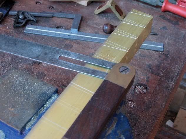
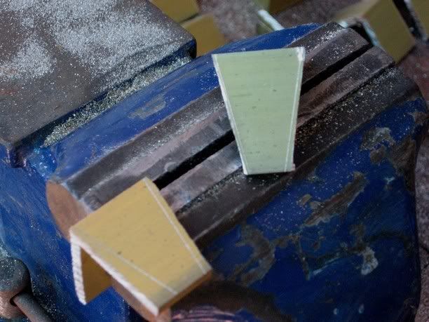
Step 1 - I am using a length of 32mm (1 17/64") wide and 3mm (1/8") thick brass angle. Here I mark off widths with a saddle square. I am aiming for a final width of about 3/4", and to get this I will lose about 1/8" in "adjustments.
Step 2 - Mark off the dovetails. These are in ratios of 1:5, 1:6, 1:7, and 1:8
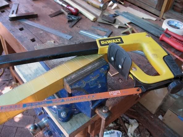
My dovetail saw!
Step 3 - cut the sections square.
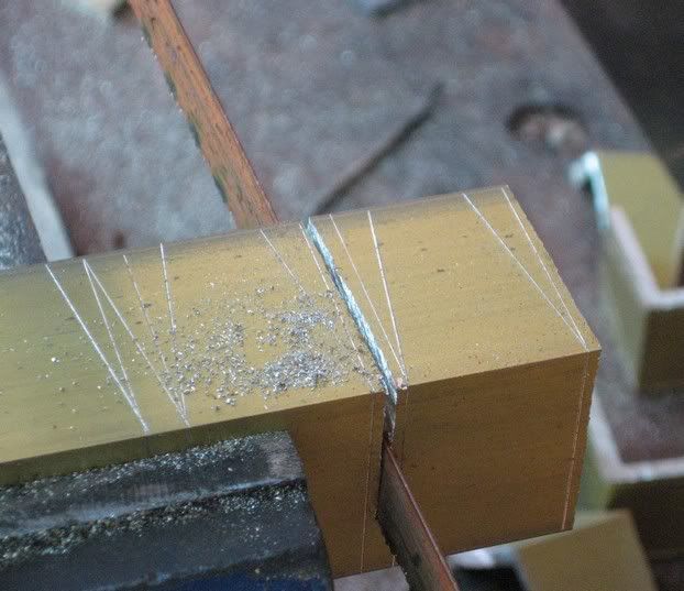
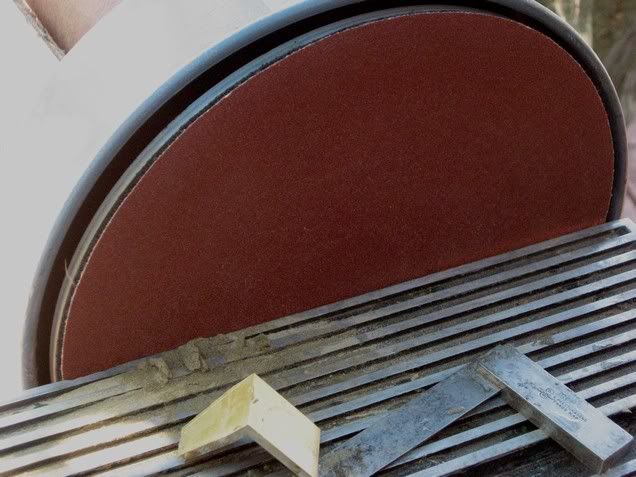
Step 4 - Remove most of the waste with the hacksaw.
Step 5 - Remove the remaining waste at the disk sander.
Step 6 - Now fine tune with sandpaper and files.
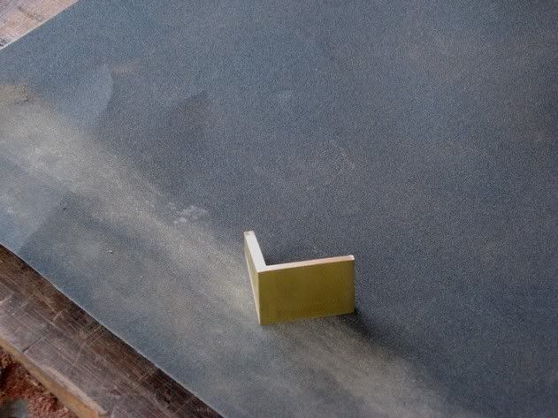
Measure the angles constantly.
Once the shape is true, I clean up all serfaces by lapping on 240 grit sandpaper, then use a fine deburring wheel. The latter leaves a smooth, very finely matte finish.
The next step is to bevel all outer edges with a file, and the final step is to stamp the ratio on the top of the guage.
Here are some images ...
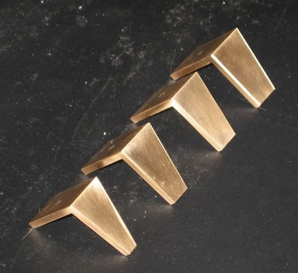
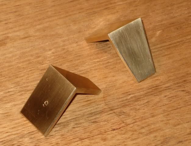
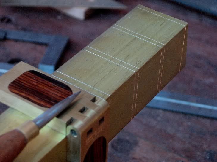
Where is the complication? Well, as I noted earlier, this guage is 3D. It is not simple L-shaped. The front "dovetail" is angled, plus the rear section is a 90 degree square. Of these angles, the 90 degree square is actually the more important one (your cuts across the board will determine whether all mates accurately). The angled front must transition smoothly into the rear square. To do this I have continued the dovetail angle into the square, so it creates an chamfer all the way up and around the sides.
You may see this more clearly here:
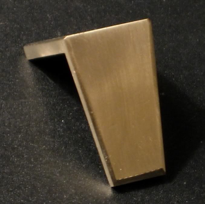
Now if I have to re-shape a dovetail angle and, say, it moves inward by .5 degree, it will move the square inward by 1mm. Similarly, if the rear square is off by 1 degree at the rear side, squaring it means having to refile the dovetail towhich it connects. Get this wrong and back you go again! It is just amazing how quickly a piece that starts off at 22 mm wide ends up at 19mm (3/4"), that is, will lose a 1/8" in width. The problem is that it can do this so quickly that it is easy to drop below 3/4", and I will reject all those gauges as too small.
The job would be so much easier if the initial machining process created the perfect angles straight off. Easy enough on a milling machine, but I only have the tools you see above.
Simple bugger, isn't it!
I must be doing it the hard way .. ideas?
Regards from Perth
Derek
-
20th April 2008 05:26 AM # ADSGoogle Adsense Advertisement
- Join Date
- Always
- Location
- Advertising world
- Posts
- Many
-
20th April 2008, 10:28 AM #2
SENIOR MEMBER
- Join Date
- Apr 2003
- Location
- Tolmie - Victoria
- Age
- 68
- Posts
- 4,010
They look good Derek - alas no suggestions.
 - Wood Borer
-
20th April 2008, 11:52 AM #3
.
- Join Date
- Feb 2006
- Location
- Perth
- Posts
- 27,800
A couple of suggestions:
1) Instead of using a normal hacksaw for cutting small pieces of brass by hand I've found using a minihacksaw gives a bit more control and produces around half the kerf of a regular hacksaw. I would also attempt the initial cut to the desired angle (instead of a square cut) with the mini.
2) Then I would make a jig to hold the pieces right way up, square in 2 dimensions and at the correct angle in the other while applying them to the sander - if you make the jig adjustable you could use it for a range of angles. That way you can get see how close you are to the desired marking.
3) Once you are close I would also consider switching to a sanding disc using very fine paper - that way you can work in a more controlled manner and creep almost up to or also right to the desired requirement. When I do my brass stuff I use new 320 grit or an old 240 grit to do this.
4) Do you also mark the insides of the brass angle? I find this is useful when filing since it reduces the number of times you have to check measurements with calipers and bevels
-
20th April 2008, 07:36 PM #4
Senior Member
- Join Date
- Jan 2008
- Location
- qld
- Posts
- 159
Very impressive Derek. I have only thought of buying these. Where is the hinged gauge from by the way? I don't want to hear that you made it, although I wouldn't be surprised!
I may have misunderstood your question, so just to clarify things, are you working on the dovetail angle and then the right angled side, or vice versa. I imagine that it would be easier to get the dovetailed side sorted first and then sand or file the right angled side to suit.
In awe
James
-
20th April 2008, 09:45 PM #5
Be inspired. Be creative. Be bold.
- Join Date
- Apr 2001
- Location
- Perth
- Posts
- 10,831
Thanks James.
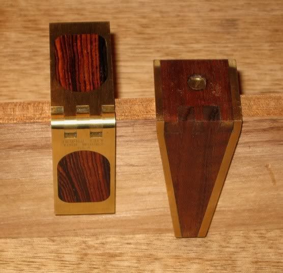
No, I did not make that saddle gauge. It comes from Bridge City Tools. However, I did make this one:
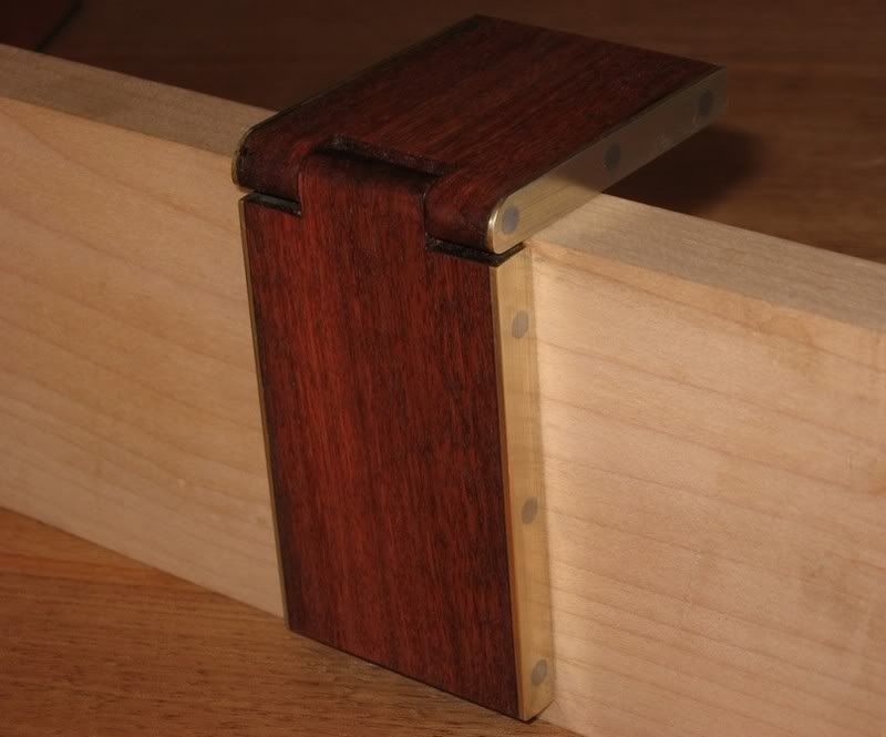
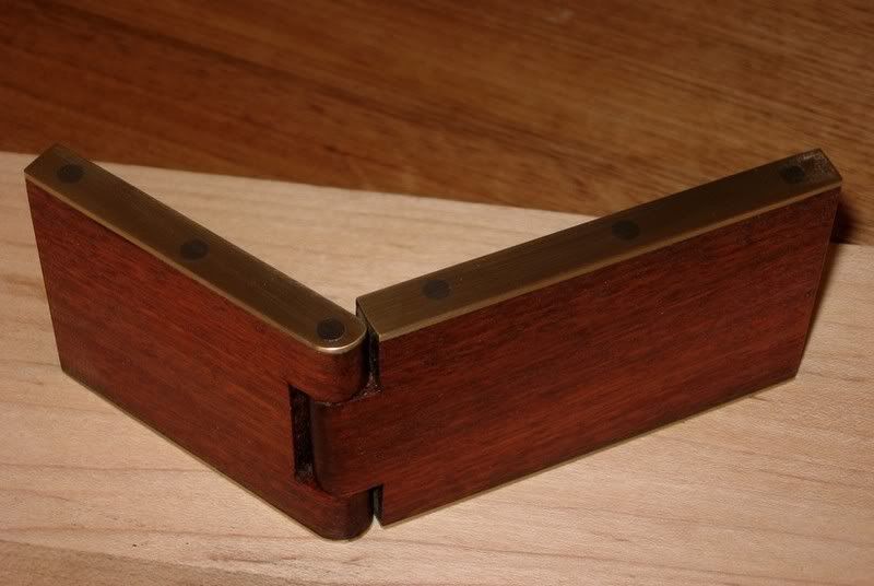
.. and this one ..
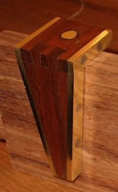
It is my little joke (a dovetailed dovetail marker). Ratio is 1:7
Here it is with the BC saddle for a better look at the latter ..
Regards from Perth
Derek
-
21st April 2008, 12:43 AM #6
 New Member
- Join Date
- Dec 2006
- Location
- Texas
- Posts
- 9
Re: More
Yours has more soul though.

John
-
4th June 2008, 10:53 AM #7
Moderate Moderater
- Join Date
- Feb 2006
- Location
- Lindfield N.S.W.
- Age
- 62
- Posts
- 5,643
I wonder whether the production difficulty could be reduced if the "square " element were square all the way round and the angled element only started from the surface of the wood. That is how your dovetailed dovetail gauge is set up.
This would separate the two elements so that adjusting one would only require a minor adjustment of the other which would be parallel to an existing line.Last edited by jmk89; 4th June 2008 at 10:58 AM. Reason: sp
Cheers
Jeremy
If it were done when 'tis done, then 'twere well it were done quickly
-
4th June 2008, 08:51 PM #8
SENIOR MEMBER
- Join Date
- Sep 2003
- Location
- Elimbah, QLD
- Posts
- 3,336
Derek,
I can undersand your decision to make a only a limited edition of your home-made dovetail markers, when Lee Valley sell a set of two for $10.50 ($20 from Carbatec). But I imagine yours will be collectors' items in the future
I have the Lee Valley set and find they work beautifully.
Rocker
-
5th June 2008, 05:25 PM #9
Be inspired. Be creative. Be bold.
- Join Date
- Apr 2001
- Location
- Perth
- Posts
- 10,831
I wonder whether the production difficulty could be reduced if the "square " element were square all the way round and the angled element only started from the surface of the wood. That is how your dovetailed dovetail gauge is set up.
Hi Jeremy
This is how I do it. The problem will occur if the dovetail angle is filed incorrectly, even by a fraction of a degree. This then send you back to reshape the square as well. So you can go back-and-forth! Pass me the whisky!
It comes down to filing skills.
I will make more in the future.
Hi Rocker
Thanks for the kind works. These tools are rarely just about whether they work. They are also about the pleasure in using something that looks good and feels good in the hand.... otherwise we would not be the tool junkies that we are! I hope that you are well.
Regards from Perth
Derek
-
5th June 2008, 05:43 PM #10
Moderate Moderater
- Join Date
- Feb 2006
- Location
- Lindfield N.S.W.
- Age
- 62
- Posts
- 5,643
Another thought Derek. I haven't tried it but it might work.
Why not make some "perfect" square and dovetailed angles that fit around a Magsquare

or the magnetic base for a dial indicator to use as fences.
Make them out of mild steel angle so that they fit exactly around the edge of the switch or base. Set it at the correct height for the surface that you want to file or sand , and turn on the magnet to hold the steel.
When the rough work on the brass is almost finished, push the brass up against the steel fence and run it against the sandpaper (with the switch or base running on the glass or whatever that the sandpaper is stuck to). When the base or switch is running flush with the glass, the brass should have the correct angle.Cheers
Jeremy
If it were done when 'tis done, then 'twere well it were done quickly
-
7th June 2008, 12:16 AM #11
GOLD MEMBER
- Join Date
- Jun 2008
- Location
- Victoria, Australia
- Age
- 74
- Posts
- 6,132
Hi Derek, Originally Posted by derekcohen

I think they look pretty slick as they are. (nice work)
However, I see your problem, I have made these from **thin** aluminium angle in the past. The material thickness exacerbates the problem.
I realise this post is now getting pretty old, and you have probably finished the first batch
If you are doing a second batch I would set up a jig (need one for each ratio) and grind to correct angle on the disk sander, at that point you have a plane intersecting with the brass angle, so the "square" section of the brass will be at an angle to the marking surface, you need to file/linish this to be at right angles to the marking surface without touching the bottom edge. I would stay away from the disk sander for this step and instead use a sanding block with 220 to square it up without disturbing the lower edge. The transition point at the apex of the angle could be smoothed if you want.
I suspect that this is probably close to what you are already doing...
If you want to do a chemical etch of a logo or something, you can use
electronic pcb photo-resists and ferric chloride.
-
14th June 2008, 09:52 PM #12
Toolmaker Extraordinaire
- Join Date
- Jun 2007
- Location
- Toowoomba, Qld
- Age
- 31
- Posts
- 2,520
I reckon you could use a table saw to cut the brass hunk so it becomes brass angle and a small square rod... Get what I mean?
-
18th June 2008, 11:51 AM #13
 GOLD MEMBER
- Join Date
- Mar 2006
- Location
- Earth
- Posts
- 3,567
What about making the markers out of flat section. This I suspect would make it easy to keep things at the correct angles then working in 3D from the start.
One finished, cut a v shaped grove (not all the way through) in the flat at the point of bending and bend.
Then solder it all into place.
Just an idea.
-
18th June 2008, 01:40 PM #14
Moderate Moderater
- Join Date
- Feb 2006
- Location
- Lindfield N.S.W.
- Age
- 62
- Posts
- 5,643
Or, instead of soldering, you could dovetail it like a Speirs or Norris plane - as described in Jim Kingshott's book or on Peter McBride's website. Then you could perpetuate the joke of the dovetail marker being itself dovetailed! Originally Posted by thumbsucker
For contrast, you could make one side brass and the other steel.
If you did, you could make a jig to hold the two pieces square and tight while you peen the dovetails - like the shoulder plane shown in ShopNotes a couple of years ago - if you don't have a copy of the article PM me and I will send it to you in a day or so.Cheers
Jeremy
If it were done when 'tis done, then 'twere well it were done quickly
-
18th June 2008, 04:27 PM #15
Toolmaker Extraordinaire
- Join Date
- Jun 2007
- Location
- Toowoomba, Qld
- Age
- 31
- Posts
- 2,520
Originally Posted by jmk89
Thought of that but I have no idea about doing dovetails in brass let alone timber. I might try it though after seeing Mr Mcbrides site..


 Reply With Quote


Similar Threads
-
FWW article on cutting half-blind dovetails - the hardcore Dark-Side way
By Rocker in forum WOODWORK - GENERALReplies: 38Last Post: 28th June 2006, 10:13 AM -
First Try at Dovetails
By RufflyRustic in forum WOODWORK PICSReplies: 48Last Post: 26th January 2006, 08:55 PM -
Hand cutting dovetails
By Ben from Vic. in forum WOODWORK - GENERALReplies: 9Last Post: 1st November 2004, 10:57 PM -
Dovetails??
By marcusl in forum WOODWORK - GENERALReplies: 28Last Post: 2nd June 2004, 08:45 PM
