

 Thanks: 0
 Likes: 0
 Needs Pictures: 0
 Picture(s) thanks: 0
Results 1 to 6 of 6
Thread: Router Lift Above the table
-
14th July 2007, 06:42 AM #1
 Deceased


- Join Date
- Jan 2006
- Location
- poland
- Age
- 78
- Posts
- 761
 Router Lift Above the table
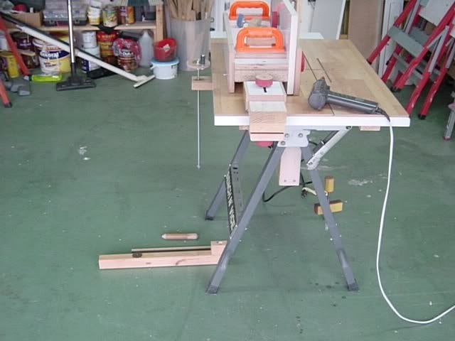
Good day
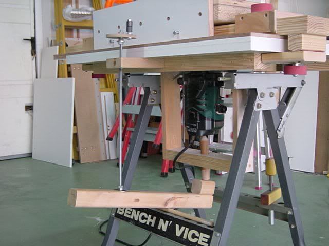
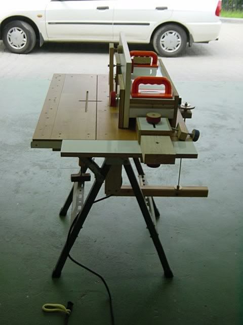
After I made the Mortising jig for the router table (a few posts down), I thought that to bent under the bench every pass to lift the bit, is too much for my old back so I made a simple lift.
The lifting mechanism is located on the right side (behind the fence) so it will not interfere with any operation.
It takes some 30 seconds to install it and I'll probably improve a few things with time and experience.
It works very smooth (after a drop of oil in the T-nut) and takes some 25 turns from "bit level with the table" (2~3 mm below) to "bit 35 mm above the table".
Regards
niki
-
14th July 2007 06:42 AM # ADSGoogle Adsense Advertisement
- Join Date
- Always
- Location
- Advertising world
- Age
- 2010
- Posts
- Many
-
14th July 2007, 08:18 AM #2
Intermediate Member
- Join Date
- May 2007
- Location
- Kitchener, Ontario, Canada
- Age
- 81
- Posts
- 26
Niki
A great and simple idea for adjusting the router. Here is an idea that you might want to try.
If you were to make a round scale to place on the handle you could dial your height in to .001 or finer if you split between the markings on your round scale.
I am not as comfortable with metric as the imperial system so will explain in inches. I am sure that you will get the idea and switch it to metric very easy.
If you have a cad program it is very easy. Say you are using 1/4-20 threaded rod then put 50 marks around the circumference and number them starting at 0 then 5, 10 up to 95, and 100 which will be back at 0. Now make a hole in the center and place it on the round wood disc that your cranking handle is on. Fasten a small pointer to the table and align it over 0.
Now when you turn it 1 full revolution (50 marks) it will raise or lower 1/20 th of an inch or .050"
I'll make a little chart
1 turn = .05"
10 turn = .5"
15 turn = .75"
20 turn = 1.00"
Now going back to the 50 marks around the edge
1 mark = .001"
2 mark = .002"
15 mark = .015"
48 mark = .048"
50 mark = .050" or 1 full turn
If you want more accuracy then go half way between mark 1 and 2 and you would have .0015".
I know that we would all like to work to the above tolerance but the wood probably changes more than that just by breathing on it.
I have used this system many times and have one installed on my planner so that I can fine tune it for thickness on the final pass to end up with exactly the thickness that I want.
Don
-
14th July 2007, 09:41 AM #3
Deceased
- Join Date
- Jan 2006
- Location
- poland
- Age
- 78
- Posts
- 761
Thank you Don
I'm not sure that your idea will work in this case.
If the threaded rod was acting directly on the router, there was no problem
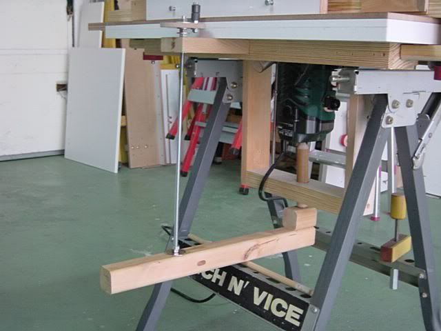
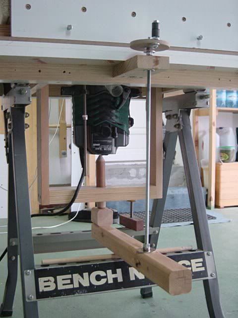
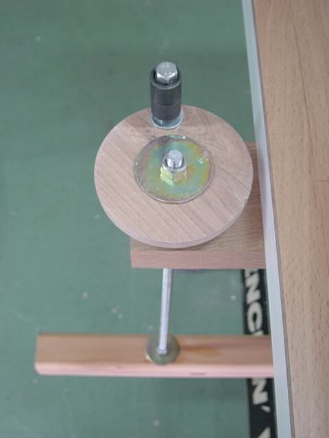
In this case we have actually two levers and we have to take into consideration the length of each lever unless, they are perfectly the same length from both sides of the hinge (this long dowel under the "Pedal"), that rolls a little bit for smooth movement of the Plunge and so, the levers lengths are changing during the operation.
To visualize it, just imagine that the length of the lever from the hinge to the router is 1' and the length from the hinge to the threaded rod is 2'...if you lower the threaded rod by 2" the router will be lifted only by 1" because of the 1 to 2 ratio of the levers lengths.
My method is to lift the bit to the final required height, checking it with caliper (that you can see on the other posts), set the depth stop, lower the bit and just turn up 2~4 turns every pass till I hit the depth stop.
Regards
niki
-
14th July 2007, 10:21 AM #4
Intermediate Member
- Join Date
- May 2007
- Location
- Kitchener, Ontario, Canada
- Age
- 81
- Posts
- 26
 Originally Posted by niki

Niki
I guess the idea is OK but I forgot about the lever action on the bottom and the changing lengths.
I guess you could measure the lengths of the pivot points and do some calculations and get close to the dimension that you want.
I guess another option would be to set the router bit flush with the table. Have pointer over the wheel and make a mark. Now raise it 1mm and make another mark then 2mm etc. etc. I guess the problem would be that it would have to be recalibrated for each different length router bit.
I will try and keep the thinking cap on and see what other ideas I can come up with.
cheers
Don
-
14th July 2007, 02:08 PM #5
SENIOR MEMBER
- Join Date
- Feb 2003
- Location
- Garvoc VIC AUSTRALIA
- Posts
- 11,464
As the lever is not traveling through much of an arc it will only affect precision very slightly. Probably so small you could ignore it.
25 turns = 35mm
so 1/12 of one turn is about .11mm
0r 1/24 of a turn is .055mm or a tad over 1.4 thou
Like ummm woodworking to toolroom standards ???????????
It would be interesting to measure the precision variation
(if you can as I suspect it will be neglible)
-
14th July 2007, 08:51 PM #6
Deceased
- Join Date
- Jan 2006
- Location
- poland
- Age
- 78
- Posts
- 761
Thank you Bob
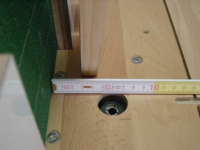
I went down to the garage and made some measuring...
With the bit flush with the table, the hinge was 24.5 mm from fixed reference point (the workbench rail).
With 10 turns up, the bit height was 15.0 mm and the hinge at 22.8 mm
With 20 turns up, the bit height was 27.5 mm and the hinge at 20.5 mm
With 30 turns up, the bit height was 40.5 mm and the hinge at 17.5 mm
According to the above measurements (all made with caliper), if 10 turns = 15 mm....20 turns should be 30 mm and 30 turns - 45 mm, but it's not so.
I'm using M8 threaded rod with a pitch of 1.25 mm per turn so every 10 turns should lift the bit by 12.5 mm...
I prefer to set the bit height with the caliper and avoid any mistakes so, the neighborhood kids will not have to learn new vocabulary in English, Polish, Hebrew, Spanish etc...
Regards
niki

 Reply With Quote

Similar Threads
-
RYOBI - Spring removal & Above Table Router Lift
By dazzler in forum ROUTING FORUMReplies: 16Last Post: 23rd October 2009, 02:24 PM -
Exacta router lift and Rout-R-lift
By zelk in forum ROUTING FORUMReplies: 8Last Post: 14th November 2007, 11:27 PM -
Router lift
By niki in forum HOMEMADE TOOLS AND JIGS ETC.Replies: 15Last Post: 27th March 2007, 10:57 AM -
Router table lift / raiser ?
By martrix in forum DESIGN & DESIGNING / GOOGLE SKETCHUPReplies: 4Last Post: 17th March 2007, 09:22 PM
