

 Thanks: 0
 Likes: 0
 Needs Pictures: 0
 Picture(s) thanks: 0
Results 1 to 15 of 40
-
11th October 2008, 12:33 PM #1
 Peter McBride


- Join Date
- Nov 2007
- Location
- Melbourne
- Posts
- 1,139
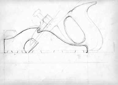
 WIP- Infill bench rebate plane with Brass sides
The bulk brass order has been finalised, and another thread about making an infill plane has brought up lots of great information. I got all inspired to make the next plane on my list, a bench rebate plane.
I'm a little embarrassed it isn't a saw... Ray, I promise my next project is the saw, perhaps before I start the infill on this plane.
I suspect most of the potential plane makers are woodworkers, and are a little intimidated by metalworking, so I have taken lots of photos and made notes of the things I do, things I usually do without thinking. I've attached a couple of the pictures to this post, and a few of the notes I've made, but I also made a couple of pages on my website with many more pictures and notes of the types of files, hacksaw blades, and other details as they came up in the process.
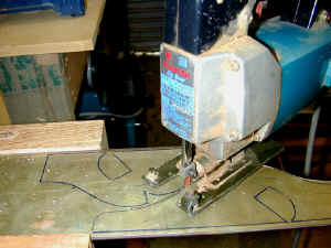
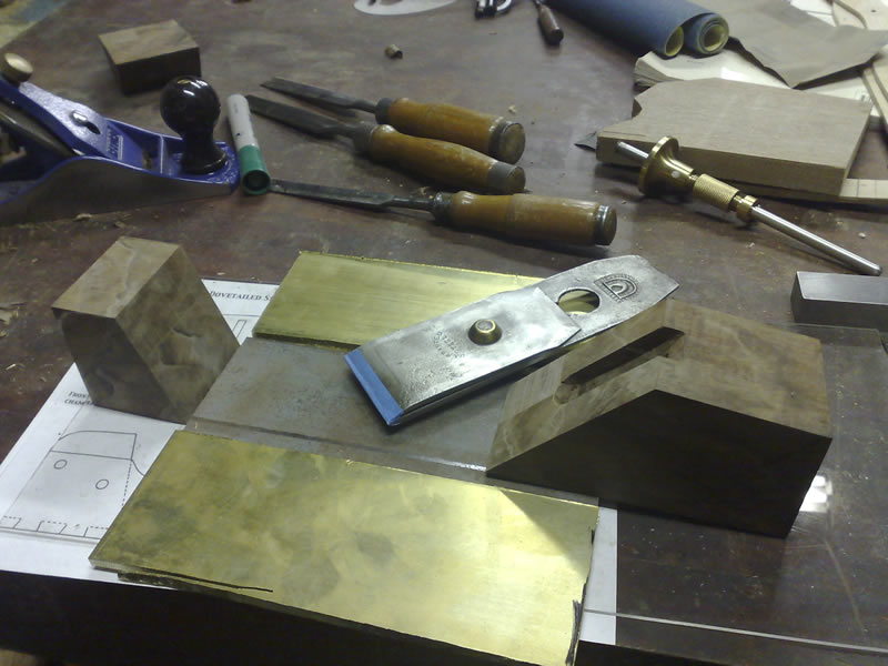
I decided to use 5mm brass for this, and cut it with a jigsaw fitted with a metal cutting blade. Slow the blade speed down and it cuts like cheese.
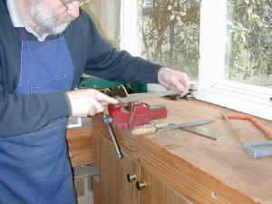
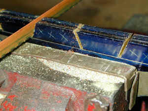
Note the height of the vice: set 30 years ago to give me a horizontal right forearm at a comfortable height.
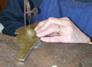
To remove the waste from the side openings, I made a couple of straight cuts with the plate in the vice (soft brass jaws), then used my jeweller's saw to cut the curves. I use a good rigid hacksaw saw and the files I've used so far are a bit of mixture.
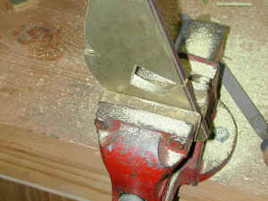
With both sides close to correct shape, they are put together into the vice for matching and finalizing the curves.

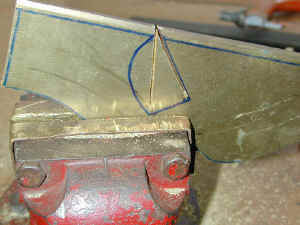
This plane will have the tails cut into the sides, and the pins in the steel base, so the sides will be fitted in from the sides of the plane onto the sole. The dovetail angle I like is 70 degrees, and the spacing is just set out by eye. One side is marked, and then the two are placed together in the vice and the marking transferred across with a small engineer's square.
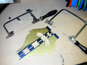
With the two plates aligned carefully and clamped together in the vice, I cut down to just above my horizontal layout line on the waste side. This line is one of the most critical for the success of the plane. It is what makes the base flat and straight. Once all these cuts are done, I go back to my jeweller's bench and cut the waste out with jeweller's saws...this takes a bit of time, about 45 minutes.
Got to my limit with images here...so for a more complete story some tips and a description of the technique I use to file the dovetails to shape.
Go to these two pages.
http://www.petermcbride.com/planemak...ch_rebate1.htm
http://www.petermcbride.com/planemak...ch_rebate2.htm
Regards,
Peter
-
11th October 2008 12:33 PM # ADSGoogle Adsense Advertisement
- Join Date
- Always
- Location
- Advertising world
- Posts
- Many
-
11th October 2008, 03:01 PM #2
GOLD MEMBER
- Join Date
- Apr 2006
- Location
- near Mackay
- Age
- 59
- Posts
- 4,639
good stuff Peter, will follow with interest.

-
11th October 2008, 05:16 PM #3
GOLD MEMBER
- Join Date
- Jun 2008
- Location
- Victoria, Australia
- Age
- 74
- Posts
- 6,132
Hi Peter,
Great post, (pity about the saw!) I have assembled all the parts I need for my in-fill, with the exception of the blade.
I have ordered a 3/16 thick parallel blade from Ron Hock.
Meantime, while waiting for that I am making (for practice) an early spiers style coffin smoother, but using a
tapered Mathieson Iron. I should be cutting out parts tomorrow and will post some pics.
One design question that I am having difficulty understanding, is I notice some designs use a steel block behind the blade riveted to the sole as additional support for the blade. (anti-chatter)
When is this needed? Do I need one?
Second question I think you answered earlier, relates to tapered blades,
I can see how the mouth opening will increase over time with a tapered blade.
So why have tapered blades at all?
When is a tapered blade desirable?
Regards
Ray
PS Apologies if these are dumb questions..
-
11th October 2008, 07:35 PM #4
SENIOR MEMBER
- Join Date
- May 2007
- Location
- Melbourne
- Age
- 58
- Posts
- 832
Thanks for sharing Peter,
I'm watching with interest.
Kevin
-
11th October 2008, 11:16 PM #5
GOLD MEMBER
- Join Date
- Mar 2005
- Location
- In the shed, Melbourne
- Age
- 53
- Posts
- 6,883
-
12th October 2008, 06:48 PM #6
Peter McBride
- Join Date
- Nov 2007
- Location
- Melbourne
- Posts
- 1,139
Ray, Originally Posted by RayG

The block behind the blade is to support the blade when the bevel is down. Traditionally the infill sole is about 4 to 6mm and that means the blade would be supported on the wooden infill and not the base...less than perfect. The block doubles the thickness of the sole so it supports the blade above the bevel.
Here is a Spiers coffin smoother ( that has been through a fire) with the block, look how he did the sides of the block an easier way to fit!

Tapered blades are used in wedged planes. That means to loosen the wedge you can tap the blade into the plane a little which will loosen the wedge, then hit the back of the plane and out it pops.
It isn't out of the question to use a tapered blade in a plane with a lever, many commercial makers did...including Stanley, in their Siegley STS branded planes in the early 1900, it just means the throat opening will widen a little as the blade is sharpened. My thinking is that if a thick parallel blade isn't available, the tapered blades are so common they can be had for a few $s, just get a handful and use them up.
Wedged infill planes usually have a tapered blade fitted.
Regards,
Peter
-
12th October 2008, 08:34 PM #7
GOLD MEMBER
- Join Date
- Jun 2008
- Location
- Victoria, Australia
- Age
- 74
- Posts
- 6,132
Hi Peter,
Here is a progress report, I had to muck about joining some pieces for the infill, I got some walnut offcuts that have some nice "marble cake" figure but were not quite big enough.
Next step is to mark out and cut the brass sides. I am not yet sure if I will go for straight sides, or become ambitious and try to bend the brass for the "coffin shape"
You can't really see it clearly, but the bit of paper underneath is the design I am copying. The bedding angle on the walnut block is 47 degrees, I will probably go for 55 degrees with the next one, that will use the hock blade.
Thanks for the explanation regarding tapered irons, I will use the Mathieson Iron for this one (just because I have it to hand).
Regarding the antichatter block, It looks pretty simple to just tig weld a block behind the blade. But I think I will do that before assembling the sides.
Regards
Ray
-
14th October 2008, 07:02 PM #8
Luban White
- Join Date
- Jan 2006
- Location
- Victoria
- Posts
- 999
Fantastic thread Peter.. thanks for sharing.
-
15th October 2008, 10:44 PM #9
Peter McBride
- Join Date
- Nov 2007
- Location
- Melbourne
- Posts
- 1,139
next instalement
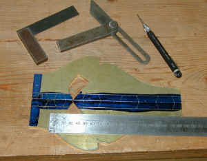
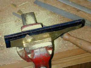
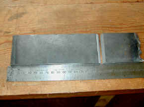
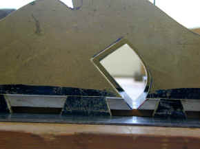
6mm ( 1/4 in) mild steel is the choice of metal for the base. The blade will be 54mm wide, and to allow a few mm each side I marked at 59 mm then used a 4 inch grinder with a cut-off wheel. I had a rethink on the blade angle and re-cut the side opening to 47.5 Deg. the Norris standard. With the bevel gauge at that angle, I marked and cut the base in two with a hacksaw, then flipped the front upside down to get the two bevels, front and back of the throat.
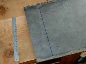
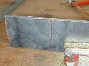
To keep everything in alignment, I will be using only one side to gauge from (next to the rule, below ). To mark the throat I used a square on that side and marked across and then filed down to that line. Then with the bevel gauge at 47.5 deg. I marked around the base and then filed flat to the front edge. I repeated this on the front piece of the base. The angle there isn't finalised yet because it will determine the throat opening, and can be altered later with higher angle to widen the throat to suite the blade...
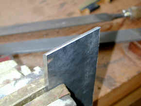
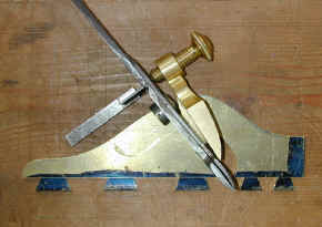
The throat opening is only about 2.5mm, and will need to be closer to 6mm. I will get that by filing a higher angle on the base, and reworking the brass just above it to get a fair curve to match in. I placed a blade set and the lever over the side plate to confirm I'm on the right path before I start to mark out the pins on the two base pieces.
For some more, and larger pictures page three is here
Would have more done today but was called unexpectedly to babysit 11 month old Jack for half the day...more fun than hacksaws and files...

Regards,
Grandpa PeterLast edited by lightwood; 15th October 2008 at 10:46 PM. Reason: layout
-
16th October 2008, 12:10 AM #10
GOLD MEMBER
- Join Date
- Jun 2008
- Location
- Victoria, Australia
- Age
- 74
- Posts
- 6,132
Hi Peter,
Jack looks like he will make some fine tools one of these days, he already has the hang of the multiple uses of the spoon...
I am still bumbling along with mine, see other thread for the gory details.
Some of the points you have made are at long last beginning to make sense...
Looking forward to the "peening and soldering" installment.
Regards
Ray
-
16th October 2008, 09:04 AM #11
Peter McBride
- Join Date
- Nov 2007
- Location
- Melbourne
- Posts
- 1,139
Ray, Originally Posted by RayG
There certainly are lots of elements that change dramatically with small variations in dimensions elsewhere. It's a function of the lever lengths and the location of pivot points. Sometimes hard to explain but much more easily seen in that trial setup above.
You mention soldering and peening together...?? there shouldn't be a need to solder the base to the sides.
Regards,
Peter
-
16th October 2008, 10:53 AM #12
GOLD MEMBER
- Join Date
- Jun 2008
- Location
- Victoria, Australia
- Age
- 74
- Posts
- 6,132
Hi Peter, Originally Posted by lightwood
I was thinking of soldering after peening, but as you say it's not necessary I won't.
Does that imply undercutting the inside of the dovetail to form double dovetails?
Regards
Ray
-
16th October 2008, 04:24 PM #13
Peter McBride
- Join Date
- Nov 2007
- Location
- Melbourne
- Posts
- 1,139
Ray, Originally Posted by RayG
When I think about it I have to go back to first principles every time....
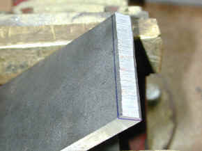
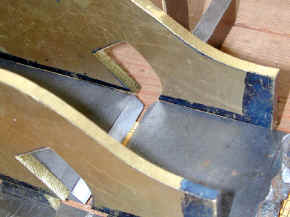
Look at the way I have mine going, I will assemble the tailed sides coming into the base from the side. They can't lift up because of the dovetail shape, but they can slide back out again. To stop that, I need to undercut the inside corner of my pin, and peen the metal into there forming a tail shape. Here is the relief cut looking from the bottom

If you do yours with the sides coming down into the base, this might help....
Here are a couple of pictures of a Spiers dovetail.
Spiers Planes have tails cut in the base and pins in sides. He cut a relief cut on both the pin and the tail, and when peened in it looks like a double tail. The sides were inserted down into the base. There was a recess filed in the corners of the tail ( on the plane base) at "a", and a recess also filed at "b" in the corners of the pin ( on the plane side plate ). The base was peened into that recess at "b". And the sides were peened into the base at "a" creating the double dovetail.
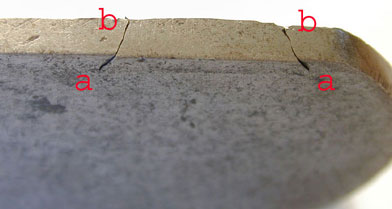

You will need to cut a relief cut like at a (above) in the base and peen the brass into it to stop the side coming up.
You might also want to cut a relief in the brass side at b
(above) and peen the steel base into the brass. It won't have to be very deep, or at a sharp angle because the steel will deform the brass as it peens in. That way you will have the appearance of the double dovetail, and get a real tight lock!
Regards,
Peter
-
16th October 2008, 04:39 PM #14
Be inspired. Be creative. Be bold.
- Join Date
- Apr 2001
- Location
- Perth
- Posts
- 10,853
Hi Peter
This is a most wonderful thread. There is nothing I can contribute (yet) but I just wanted you (and Ray) to know that I (we) hang on your every word. Keep it going.
Regards from Perth
DerekVisit www.inthewoodshop.com for tutorials on constructing handtools, handtool reviews, and my trials and tribulations with furniture builds.
-
16th October 2008, 04:42 PM #15
GOLD MEMBER
- Join Date
- Mar 2005
- Location
- In the shed, Melbourne
- Age
- 53
- Posts
- 6,883


 Reply With Quote


Similar Threads
-
Infill Shoulder plane
By Zsteve in forum ANTIQUE AND COLLECTABLE TOOLSReplies: 5Last Post: 4th April 2008, 01:11 PM -
infill plane
By John Saxton in forum HAND TOOLS - UNPOWEREDReplies: 1Last Post: 24th October 2006, 04:25 PM -
Renovation of an infill plane
By derekcohen in forum HAND TOOLS - UNPOWEREDReplies: 14Last Post: 19th April 2006, 11:57 PM -
Building an Infill Plane
By sam63 in forum HAND TOOLS - UNPOWEREDReplies: 23Last Post: 18th January 2006, 02:31 PM -
My Stanley #4 Infill plane
By derekcohen in forum WOODWORK PICSReplies: 5Last Post: 21st June 2003, 11:10 PM
