

 Thanks: 0
 Likes: 0
 Needs Pictures: 0
 Picture(s) thanks: 0
Results 1 to 15 of 15
Thread: Adding a DRO to the lathe
-
3rd January 2010, 08:47 PM #1
 Retired Member


- Join Date
- Nov 2006
- Location
- Bendigo Victoria
- Age
- 80
- Posts
- 16,560
 Adding a DRO to the lathe
A little while ago I was looking at buying a VFD for a yet to be purchased wood lathe.
In searching on Ebay I came across a VFD and 3ph motor for sale which also included a 2 axis DRO with 2 glass scales (as sold by Hafco).
As I had plans to add a DRO to my metal lathe anyway, I placed a (very) late bid and was successful. I didn't fully understand all the capabilities of this (homemade) DRO and controller, it wasn't until I read the guy's website description properly that I got a feel for all this system can do.
Now that Christmas is out of he way I decided to allocate a few days to installing the DRO part, not altogether sure whether I'll install the VFD and 3ph motor on the metal lathe as well at this stage. Might just keep that for when I eventually find the right wood lathe.
Although it would be rather interesting to have fully integrated DRO and speed controller, time will tell which way I'll jump.
For now I concentrated on installing the DRO and glass scales and associated brackets which came with the system. As this came off an almost identical 9x20 lathe most of the figuring out work was already done for me.
First order of business was to remove the lathe from the bench it normally sits on so that I would have easy access to the back where most of this gear will go.
I also took the opportunity to replace the existing speed control pot as it was a rather clunky component with no definite start and stop points. Having done that the occasional flashing of the speed readout also disappeared.
Removed the splash guard and then the cross slide.


This was to enable me to drill and tap a couple of mounting holes for the Y axis on the cross slide.


Trial mounting of bracket on cross slide

-
3rd January 2010 08:47 PM # ADSGoogle Adsense Advertisement
- Join Date
- Always
- Location
- Advertising world
- Age
- 2010
- Posts
- Many
-
3rd January 2010, 10:39 PM #2
SENIOR MEMBER
- Join Date
- Aug 2008
- Location
- Charlestown NSW
- Age
- 65
- Posts
- 899
Fred
Thanks for posting this. Look forward to the rest.
Good to see someone has been spending their time industriously.
regards
bollie7
-
3rd January 2010, 10:46 PM #3
Retired Member
- Join Date
- Nov 2006
- Location
- Bendigo Victoria
- Age
- 80
- Posts
- 16,560
Next the bracket for the X axis is installed

A trial installation of the X axis support bracket

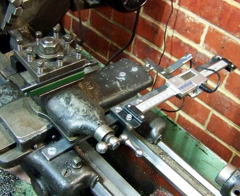
Then the support bar for the X axis glass scale (50x10mm aluminium)

The glass scale is installed and the support bracket tested


It needs to be perfectly aligned in parallel with the lathe bed, this done by mounting the dial indicator on the carriage and moving it end to end checking the deviation and making adjustments.

After installing the swarf guard on the X axis scale, the Y axis scale is installed

It also has be checked for alignment to the cross slide with the dial indicator


Next the DRO display box needs to be mounted
-
4th January 2010, 02:18 AM #4
GOLD MEMBER
- Join Date
- Jul 2006
- Location
- Port Huon
- Posts
- 2,685
Fred,
In view of the very professional job you're doing there, I'm going to have to rethink my plans on installing the DRO on the mill.
Will your metal lathe handle a 3HP motor? Upgrading the motor in my lathe is something I'd like to do as changing the drive belts around to change speed is getting to be a real pain.Geoff
The view from home
-
4th January 2010, 08:23 AM #5
Retired Member
- Join Date
- Nov 2006
- Location
- Bendigo Victoria
- Age
- 80
- Posts
- 16,560
Thanks Geoff, don't forget though that a large part of the job was already done for me Originally Posted by snowyskiesau


I haven't had to change belts on my lathe as I bought the EVS version of the 9x20. This has proved to be a boon, just the twirl of a knob and you have the speed you want.
I really don't know why anyone would want to buy a belt change lathe if there is an EVS version. In the case of the Steelmaster, even the price difference is not a disincentive, ATM it only costs $100 more than the belt driven model.
As to a 3hp motor, I don't know. My current motor is 1hp and I haven't stalled it yet. This may be due to the fact that the EVS also incorporates constant speed/torque.
The 3ph motor that came with the DRO package is also a 1hp. I think the limitation would be physical size. The 1hp 3ph is much larger than the 1 hp motor already on the lathe, so I don't know how big a 3hp one would be .
-
4th January 2010, 08:59 AM #6
Retired Member
- Join Date
- Nov 2006
- Location
- Bendigo Victoria
- Age
- 80
- Posts
- 16,560
The package came with a rather large control box that holds all the electronics as well as the display. It uses a snazzy adjustable bracket. After some tiral and error I decided to mount it on the lathe itself, at the back of the headstock, using the existing bolt holes for the back cover.


I used some 6mm aluminium plate I had to hand and drilled mounting holes matching the mounting on the lathe, then added mounting holes for the bracket.


-
4th January 2010, 10:24 AM #7
Retired Member
- Join Date
- Nov 2006
- Location
- Bendigo Victoria
- Age
- 80
- Posts
- 16,560
Finally got ot mount the control box on the lathe, can't mis it!!


All that remains now is:
Some tidying up of the cabling
Re-mounting the lathe on the bench, I will bring it more forward and raise it on 25mm blocks. I found that the way it was mounted was too close to the bench causing interference with the Norton gear box lever, as well as with the powerfeed lever.
I also will need some more room behind the lathe because of the Y axis scale.
Also need to either modify the existing splash guard or make a new one. For now I'll make a temporary guard over the motor until I work out the best way of doing this.
-
4th January 2010, 11:46 AM #8
Senior Member
- Join Date
- Dec 2009
- Location
- Melbourne
- Posts
- 100
Looks good, a nice compact little unit.
A mate on another forum picked up a similar thing on eBay a couple of days ago. Ill let his posts from another forum do the talking:
Originally Posted by Sam-Q
Originally Posted by Sam-Q
-
4th January 2010, 04:15 PM #9
GOLD MEMBER
- Join Date
- Jul 2006
- Location
- Port Huon
- Posts
- 2,685
Sorry, a bit of christmas dyslexia crept in there. I saw 3ph as 3hp. Originally Posted by Big Shed
Geoff
The view from home
-
4th January 2010, 04:23 PM #10
Good Wood Ruined!
- Join Date
- Jan 2004
- Location
- Towradgi
- Posts
- 4,839
Fred, does it make a good cup of coffee?
Look at the Woodfast's for a Wood Lathe. . . I know you wander over the border from time to time . . .Pat
Work is a necessary evil to be avoided. Mark Twain
-
4th January 2010, 04:51 PM #11
Retired Member
- Join Date
- Nov 2006
- Location
- Bendigo Victoria
- Age
- 80
- Posts
- 16,560
Don't know Pat, wouldn't want to do anything too fancy! Originally Posted by Pat

Yes, I have looked at the Woodfast lathes. Love the big 910 like yours, but total overkill for what I want, and it is too high for me, great quality lathe though.
As for the 905, have looked at both the EVS and the manual belt change models, a total of 3, all had excessive side to side "slop between tail stock and bed, not for me thanks
-
5th January 2010, 10:54 PM #12
GOLD MEMBER
- Join Date
- Oct 2006
- Location
- Trinity Beach, Qld.
- Age
- 76
- Posts
- 5,313
Fred, some great thinking and work there, thanks for all the pictures, if I ever have a larger shed and want to do the like I will get BigShed to come and "demonstrate" !!!
. Amos Good, better, best, never let it rest;
Til your good is better, and your
better, best.
-
16th January 2010, 01:09 PM #13
Retired Member
- Join Date
- Nov 2006
- Location
- Bendigo Victoria
- Age
- 80
- Posts
- 16,560
Got the lathe back on the bench, took the opportunity to raise it on 25mm MDF blocks.

At the same time i moved the position of the lathe to the front of the cabinet top to give more room for the Y axis scale and modified splash guard (to come)
The extra 25mm makes a real difference to the working height which I had found to be a bit low, but more importantly it gives more room for the Norton gearbox lever and the X axis power feed lever, which hit the splash tray.
It also provides extra height for a bigger oven tray to be inserted under the lathe, assisting with removing swarf. I had a smaller and lower oven tray before but this one works a lot better

When I had all this in position I decided I didn't like the DRO sitting behind the headstock. First of all it obscured the tool board, not an insurmountable problem, but more importantly iw wasn't easy to read in the position.
After some experimentation I re-located it, using the supplied bracket, to the right of the tool board and angled slightly towards me.

I also took the opportunity to tidy the cabling using some rectangular conduit with removable top from Bunnies.

Used this setup for the first time yesterday and I was cery impressed the DRO. Very easy to turn to a given size and determine the length of a tenon on bushes etc.Hardly used the lathe dials at all, and a much reduced use of claipers and the digital indicator, so it was all worth the effort.
Also started on modifying the rear splash guard. Becuase of the 2 glass scales the standard is no longer suitable. Started by making to 2 cuts and bending the bottom part back to make room for the Y axis scale, but that wasn't successful, so decided to be a bit more drastic and cut the left side right off, giving me protection for the motor.

Was at the local 2nd hand dealer, a real treasure trove that one, and found a 1m sq sheet of 3mm PVC and will fashion the rest of the splash guard out of that. With a bit of heat it will be easier to bend than sheet metal without a brake.
To be continued................
-
26th January 2010, 03:35 PM #14
Retired Member
- Join Date
- Nov 2006
- Location
- Bendigo Victoria
- Age
- 80
- Posts
- 16,560
One problem I was experiencing with the DRO was that the readout was rather dim, particularly as I have a fluoro mounted right above the lathe.
Queried the guy I bought it from, also the designer/builder, and he informed me that the firmware inside the DRO would have to be updated to change the brightness of the readout.
Delivered the DRO to him on Sunday morning and picked it up on my way home on Sunday afternoon. Brightness is now spot-on for these old eyes
Another job to be completed was the splash guard, it had to be modified to allow the Y-axis glass scale to travel along the X-axis.

I basically cut the splash guard in 2, see photo in previous post and used some 3mm PVC sheet to attach the 2 parts with a suitable slot to allow the Y-axis scale to travel along it. I also made the spash guard slightly longer to allow it to rest on the bench just outside the drip tray.

Close up of the slot and PVC sheet

-
29th January 2010, 10:44 PM #15
New Member
- Join Date
- May 2008
- Location
- Sth Morang Melbourne
- Posts
- 8
Hi Fellas ! Since you getting Fancy with your Metal Cutting Lathes Iwill inform you that if you want to get accuracy and Contour Machining you can Mount a 1 1/2 " Stroke Mimik Copy Lathe on where your Compound Slide is Bolted to. This then allows you to machine all type of Shapes like model Railway wheels . Round Balls. as well as the every day steps and Tapers Acurate Diameters to within .0005 on Diameters internal as well as external. Mimik Copy slides are World Wide known as the Top Dog of Tracer Slides for Lathes and Milling Machines, Vertical Turret Milling Machines etc. Want to know more ? Just give me a Yodel and I will send you some info. Make Chips Fly . Mimik will cut your Machining Time down to about half of normal Manual Machine Times. We use them to recut Roll Profiles to a very accurate Profile within 10th of a Thou. Happy Turning
Your friend Reg Shan


Similar Threads
-
Adding A Pic To Your Post
By ubeaut in forum FORUMS INFO, HELP, DISCUSSION & FEEDBACKReplies: 34Last Post: 12th February 2010, 07:40 PM -
Adding a third O/S
By Mulgabill in forum COMPUTERSReplies: 7Last Post: 18th September 2009, 07:18 PM -
Adding photos
By Flowboy in forum WOODWORK PICSReplies: 8Last Post: 3rd July 2006, 09:16 AM
