

 Thanks:
  Likes:
  Needs Pictures:
  Picture(s) thanks:
Results 1 to 15 of 55
-
20th December 2014, 04:55 PM #1
 Senior Member


- Join Date
- Sep 2009
- Location
- Penrith, NSW
- Posts
- 116
 Calling all electrical experts - DC motor conversion
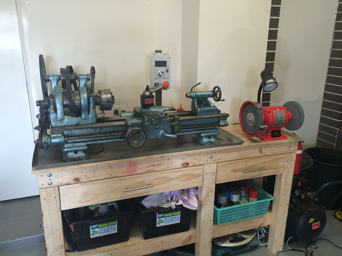
Great day for the Hercus today, not only did I finally get all my imperial gears (big thanks to pipeclay) but I took a gamble on an eBay auction for a treadmill:
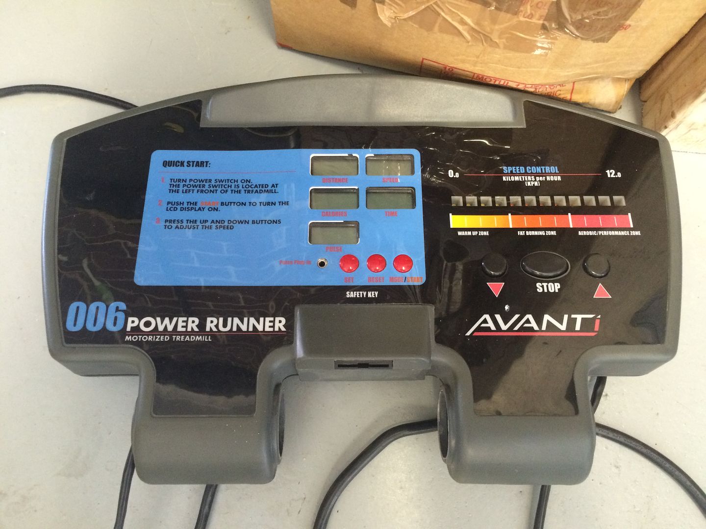
Plan for the treadmill was to try my hand at a DC motor conversion. 99c later I was the proud owner of a Avanti 006 Treadmill:
My father in law hand already given me a treadmill motor and this was designed to provide the electrical bits but unfortunately the motor he gave me was 0.5hp AC
Shame, because I really needed to replace the old motor on the lathe:
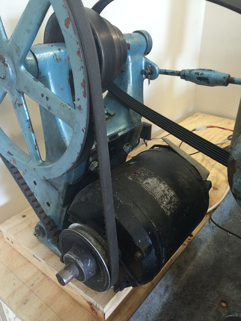
Pulled the Avanti apart this afternoon and was delighted to find this with a fan attached at the end too:
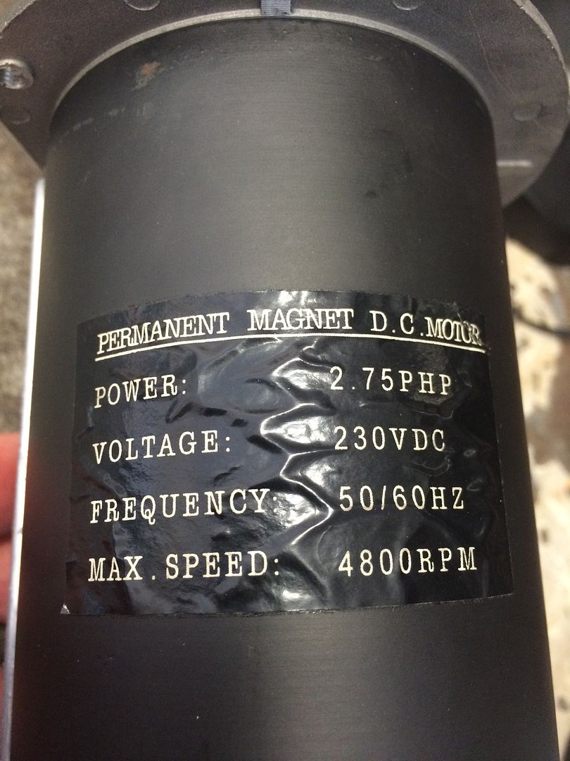
A bit too powerful for my little 9" lathe, but I plan on keeping the flat belt, so that will provide a little insurance against the hp.
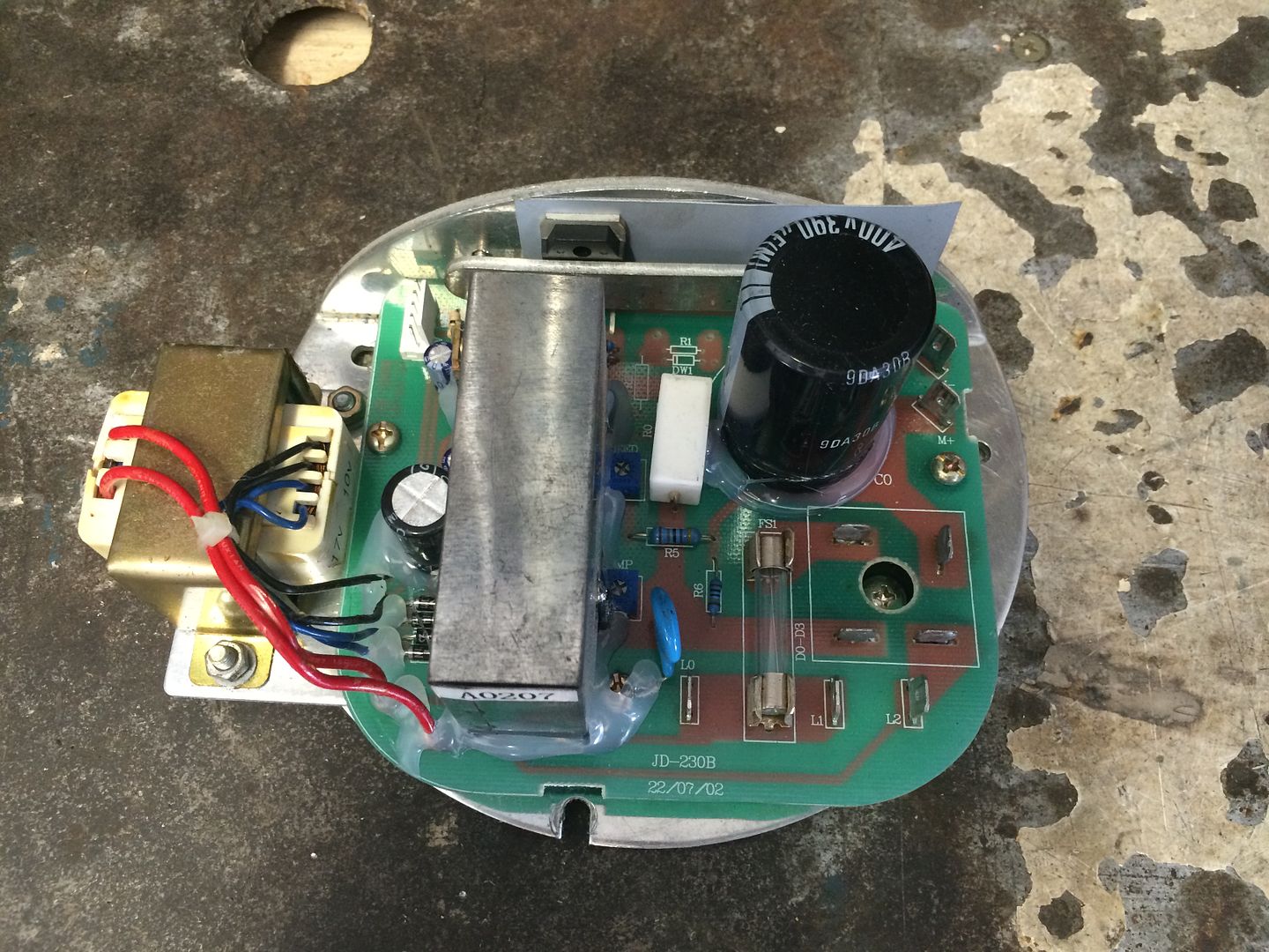
I pulled the pwm and tested the motor:
The motor made a horrible noise, which was the reason nobody bid on it, I pulled the motor apart and found something had been through it. There was some damage to some of the inner motor spindle. I filed down some nicks and flattened the brushes and it worked perfectly afterwards. RESULT!
Sent from my iPhone using Tapatalk
-
20th December 2014 04:55 PM # ADSGoogle Adsense Advertisement
- Join Date
- Always
- Location
- Advertising world
- Posts
- Many
-
20th December 2014, 05:01 PM #2
Senior Member
- Join Date
- Sep 2009
- Location
- Penrith, NSW
- Posts
- 116
Calling all electrical experts - DC motor conversion
Now to the questions.
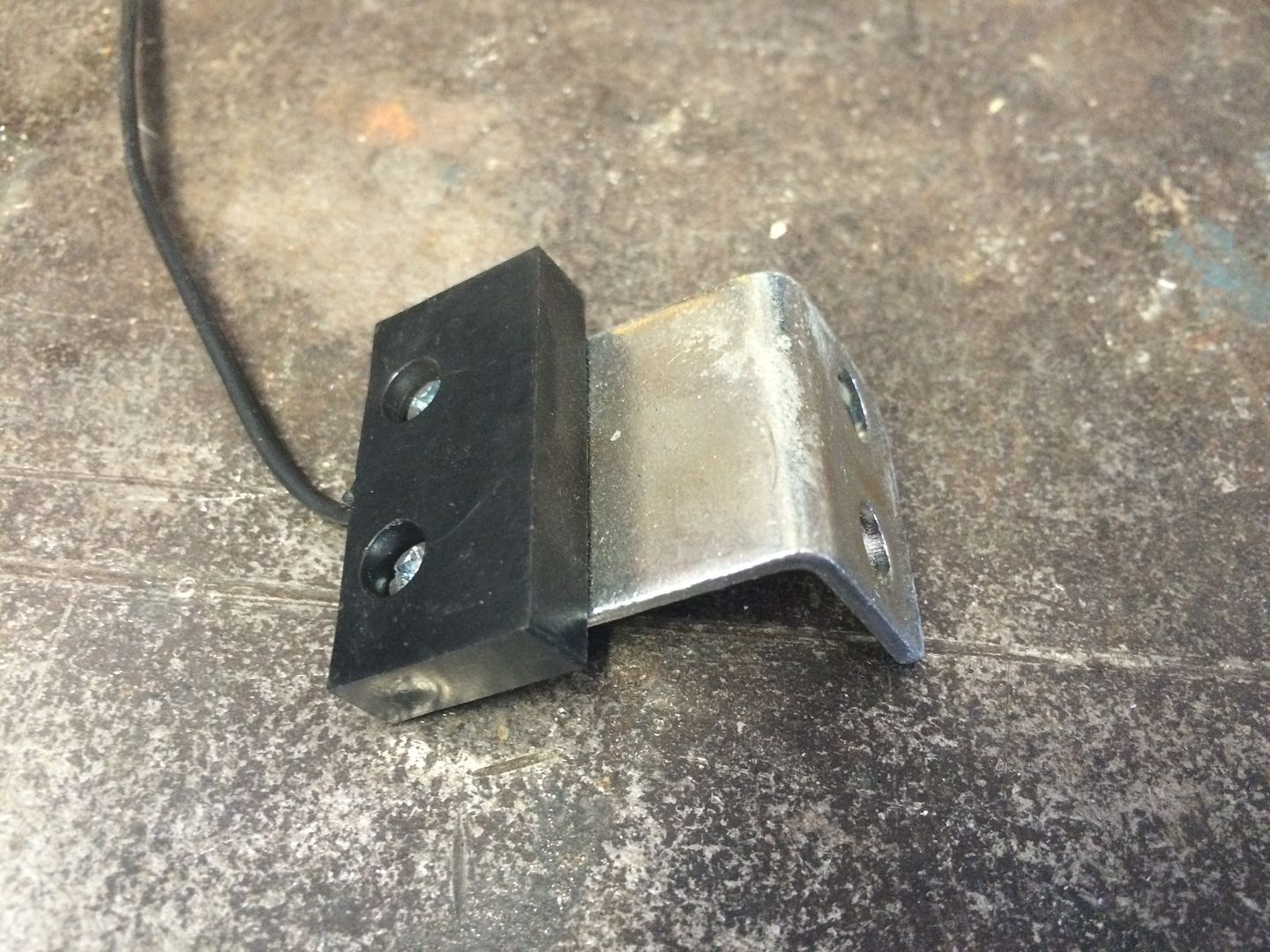
1) There is a Hall effect sensor that connects to the PWM. What is this for and should I look to keep it?
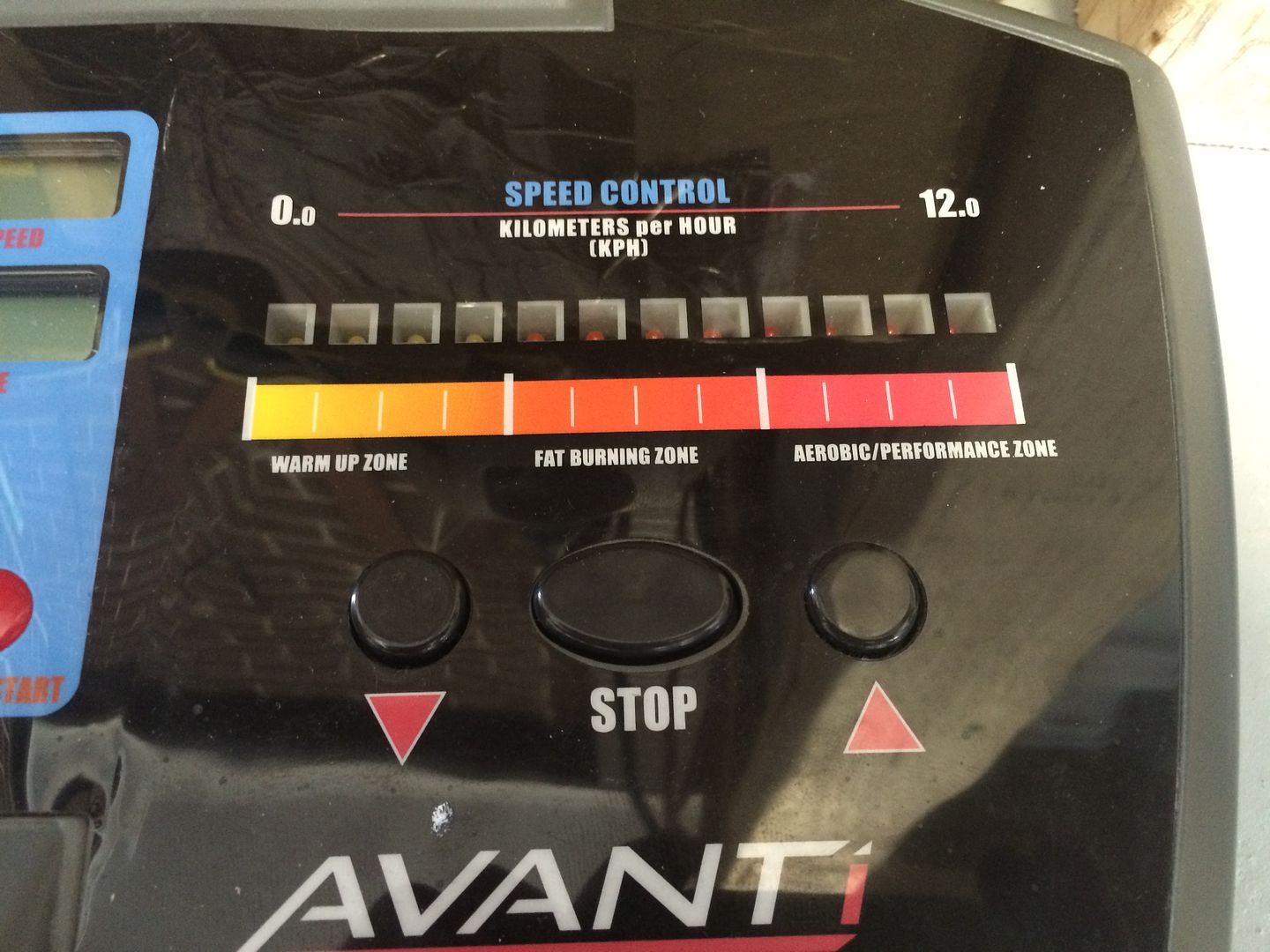
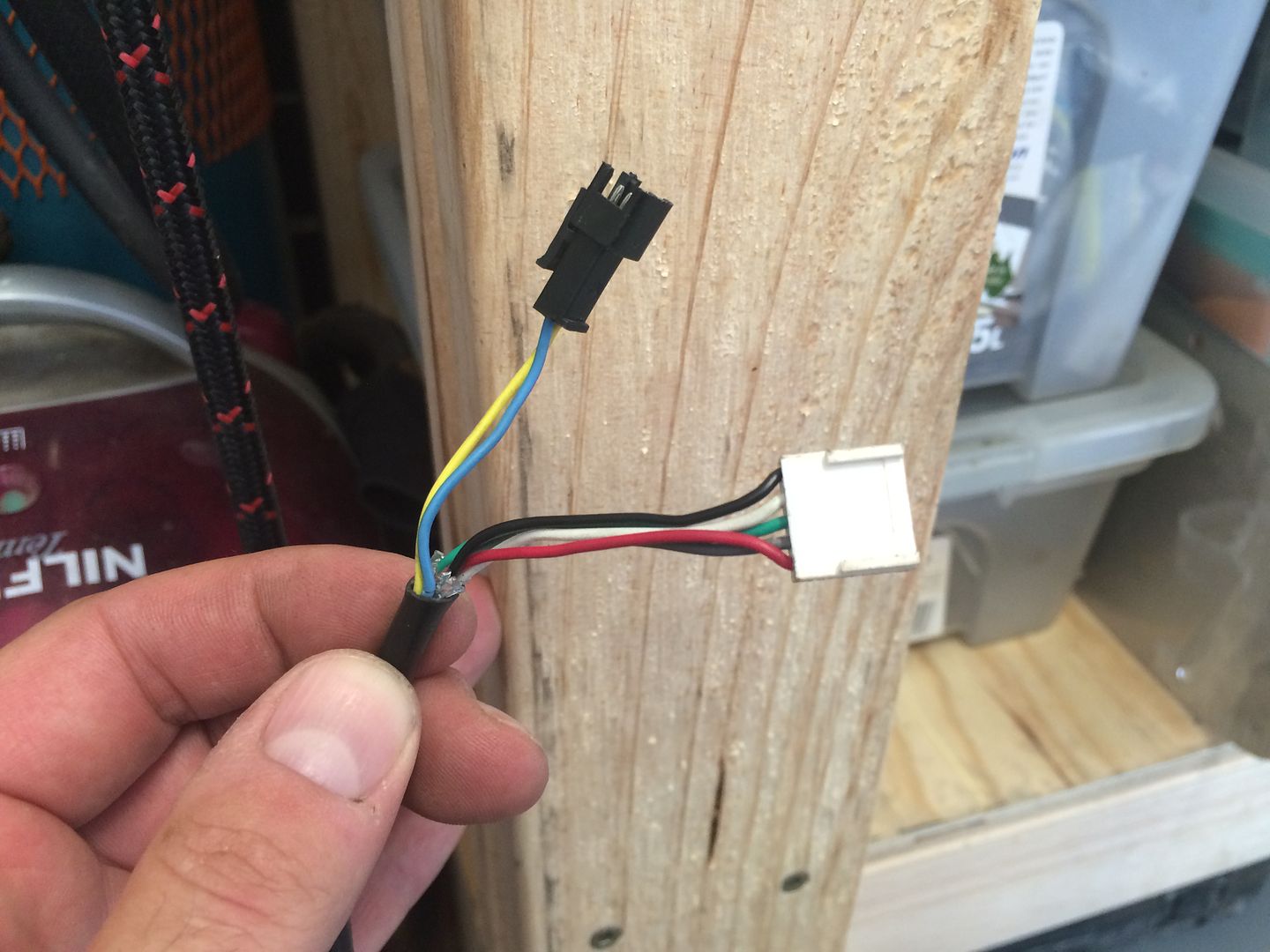
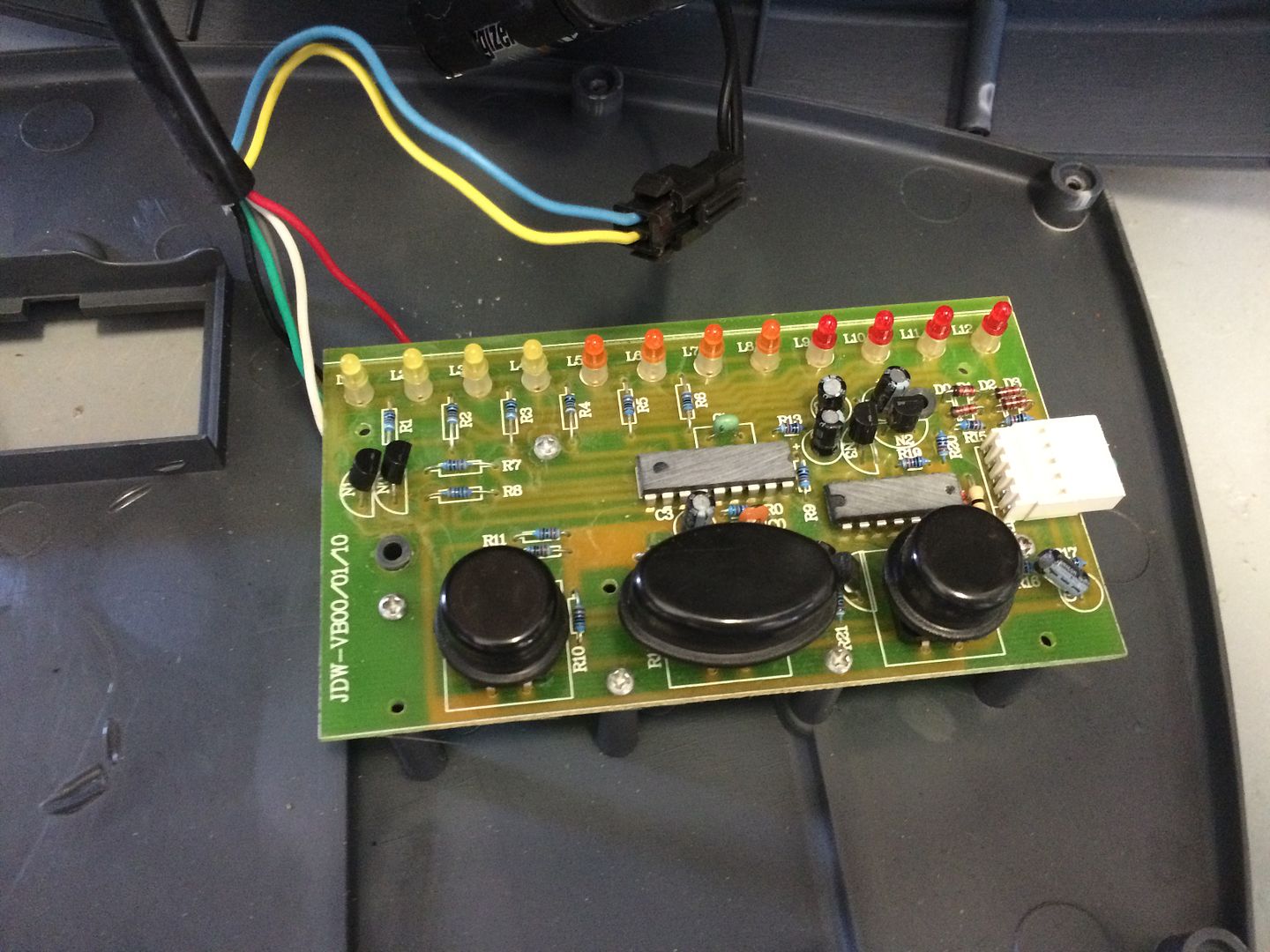
2) This is the speed control module. I am keen to remove this and use my potentiometer instead. There are 5 wires to the speed control unit and I would assume 2 are the power for the LEDs and maybe 3 could control the speed. But really I have no idea. Anyone know what's going on here and if I can replace with a pot?
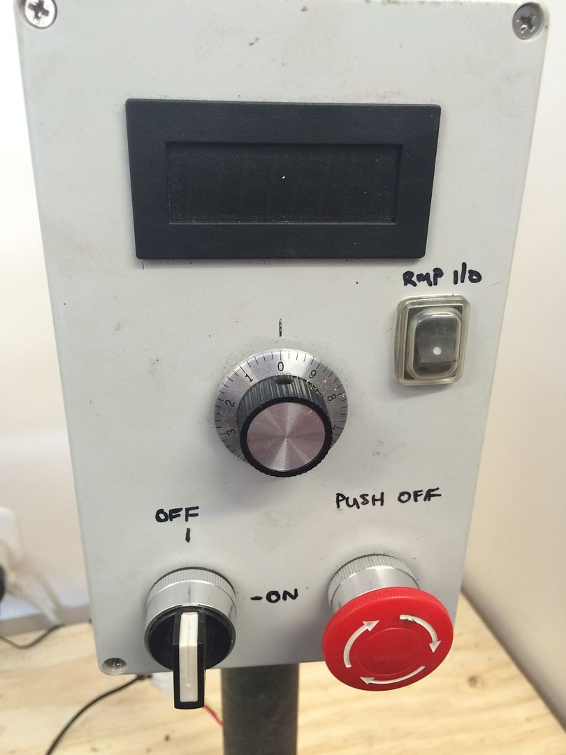
Front panel
Wires into speed control and Hall effect sensor:
Hall effect pickup:
Speed control module:
The pot I'm trying to use:
Sent from my iPhone using Tapatalk
-
20th December 2014, 05:11 PM #3
GOLD MEMBER
- Join Date
- Jun 2008
- Location
- Victoria, Australia
- Age
- 74
- Posts
- 6,132
The hall effect sensor is probably speed feedback. Might be worth keeping.
Ray
-
20th December 2014, 05:15 PM #4
Senior Member
- Join Date
- Sep 2009
- Location
- Penrith, NSW
- Posts
- 116
Thought that might be the case. I assume it varies voltage to maintain speed. Originally Posted by RayG

Sent from my iPhone using Tapatalk
-
20th December 2014, 05:27 PM #5
The Laird
- Join Date
- Jan 2007
- Location
- Katoomba NSW
- Posts
- 4,774
I'll have a go.
Prox switch is speed feed back as mentioned. I think for the digital display only.
I think the speed control is multi speed not variable.
Pressing the up/down buttons increases or decreases a counter that varies the pulse width to a pre determined value that corresponds to the counter value..
Pressing the stop button resets the counter to zero.
Only a guess but if it is correct I don't think you could adapt a pot easily if at all.
-
20th December 2014, 05:30 PM #6
Senior Member
- Join Date
- Sep 2009
- Location
- Penrith, NSW
- Posts
- 116
Calling all electrical experts - DC motor conversion
Got it NCArcher. Looks like I need to incorporate the button module into my control box then.
I will check where the wiring goes for the hall sensor too. If it goes to the display can I assume it's not of benefit as it doesn't interact with the motor?
Thanks for the advice.
-
20th December 2014, 06:01 PM #7
The Laird
- Join Date
- Jan 2007
- Location
- Katoomba NSW
- Posts
- 4,774
Again, I'm only guessing.
If the prox switch goes straight to the display then I think it's pretty safe to say it will have no effect on speed control.
-
20th December 2014, 06:51 PM #8
Senior Member
- Join Date
- Sep 2009
- Location
- Penrith, NSW
- Posts
- 116
Yeah I does go straight to the display.
Sent from my iPhone using Tapatalk
-
20th December 2014, 07:39 PM #9
The Laird
- Join Date
- Jan 2007
- Location
- Katoomba NSW
- Posts
- 4,774
I've been googling. The motor control board appears to be a generic one. probably made in china. I'm almost certain that you can connect a pot in place of the speed control unit. I'm just not sure yet how to do it. The red and blk wires are probably +5V and 0V supplying the speed control board. The Grn/Wht/Gry wires are the speed control inputs. It may be as simple as placing a 10k pot on these terminals but I can't find any specific info or cct diagrams on these boards.
-
20th December 2014, 08:35 PM #10
Senior Member
- Join Date
- Sep 2009
- Location
- Penrith, NSW
- Posts
- 116
Calling all electrical experts - DC motor conversion
Interesting. Maybe the pots not completely out yet then. I assume I have no need for power if I replace the board with the pot?
Eg remove the red/black (if they are power for the board) and work out which ones go to which of the 3 connections on the pot.
Is there a way to test resistance across each wire to see which is ground and which is the in/out for the pot wiring when the board is live?
-
20th December 2014, 09:08 PM #11
Senior Member
- Join Date
- Sep 2009
- Location
- Penrith, NSW
- Posts
- 116
Calling all electrical experts - DC motor conversion
Looking at the back of the board there is a common connection between all the switches (up, down, off). Would that correspond to the ground on the pot?
If so what's the risk of I get the other 2 connections on the pot mixed up?
-
20th December 2014, 09:11 PM #12
Blacksmith, Cabinetmaker, Machinist, Messmaker
- Join Date
- Dec 2011
- Location
- Canberra
- Age
- 40
- Posts
- 4,467
Hi Neevo,
The biggest problem you will have by far is keeping to motor cool. Have a look here https://www.woodworkforums.com/f65/mars-lathe-dc-motor-conversion-159263
I ended up cooking my motor, i think the braking didn't help but i just could not keep it cool.
Nearnexus may still have some KBIC controllers left if you want an easy hookup solution. They are not that expensive.
Cheers,
Ew1915 17"x50" LeBlond heavy duty Lathe, 24" Queen city shaper, 1970's G Vernier FV.3.TO Universal Mill, 1958 Blohm HFS 6 surface grinder, 1942 Rivett 715 Lathe, 14"x40" Antrac Lathe, Startrite H225 Bandsaw, 1949 Hercus Camelback Drill press, 1947 Holbrook C10 Lathe.
-
20th December 2014, 09:33 PM #13
Senior Member
- Join Date
- Sep 2009
- Location
- Penrith, NSW
- Posts
- 116
Cheers Ew. I will keep an eye on that. Just run the motor on the bench with no cooling and it didn't even get warm after 2 mins on 20% power. No idea how that will translate in the real world though.
Also tried to wire up the pot but it did nothing. Looks like I might use the board for the moment, plus I get cool lights to see where the motor is at.
-
21st December 2014, 12:35 AM #14
GOLD MEMBER
- Join Date
- Aug 2010
- Location
- Bendigo
- Age
- 72
- Posts
- 1,986
I'm no expert, but for a pot to work, the speed control would have to react to either a variable resistance or a variable voltage or a variable current.
The output of the push button controll might be any of these or it might be digital (some sort of numerical count) - in which case a pot is not going to work.
I suggest you firstly put a multimeter across the control lines and if that doesn;t tell you anything find someone with an oscilloscope to have a look at what the output is doing. That would clear it up I think.
Good luck and let us know what you find out!Cheers,
Joe
9"thicknesser/planer, 12" bench saw, 2Hp Dusty, 5/8" Drill press, 10" Makita drop saw, 2Hp Makita outer, the usual power tools and carpentry hand tools...
-
21st December 2014, 08:52 AM #15
Senior Member
- Join Date
- Sep 2009
- Location
- Penrith, NSW
- Posts
- 116
This is probably getting a little beyond my abilities. Plus the original board works a treat and has speed indicator leds.
I think I will rework/make my control box and include the board as the speed control instead.
Cheers all.
Ew I will let you know how the temp goes on the motor. I need to make a fan for it as the one I have is the wrong way round as I need to reverse the motor.


Similar Threads
-
Calling TIG experts - motorbike related.
By chancho196 in forum WELDINGReplies: 12Last Post: 25th May 2012, 11:19 AM -
Calling all Nail Gun Experts
By lesmeyer in forum NOTHING AT ALL TO DO WITH WOODWORKReplies: 6Last Post: 13th May 2012, 11:43 PM -
Calling any and all Stanley experts
By elanjacobs in forum HAND TOOLS - UNPOWEREDReplies: 1Last Post: 26th July 2010, 10:13 PM -
Calling all Domino Experts
By lesmeyer in forum FESTOOL FORUMReplies: 16Last Post: 28th June 2009, 08:14 PM
