

 Thanks:
  Likes:
  Needs Pictures:
  Picture(s) thanks:
Results 1 to 15 of 26
Thread: Mill coolant tray
-
23rd April 2013, 04:54 PM #1Dave J Guest
 Mill coolant tray
Hi,
Well I finally got around to finishing off the coolant tray with the help of my grandson (little David) as he is here for the week.
Now to use the famous words of Paul Hogan in Crocodile Dundee
Thats not a coolant tray

This is a coolant tray.

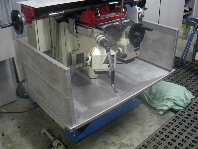
The main aim of building this was to have a coolant tray that did not use the base of the mill for the coolant to run into, and it was able to be taken off to be degrease outside, so it needed to come off easy.
I had a sheet of 1200 x 3600 x 0.9mm thick aluminum sheet I was given from my nephew a few years back that I had always planned to make this but have only just got around to it.
After planning it out I cut it all up and found it used the lot all but a small off cut.
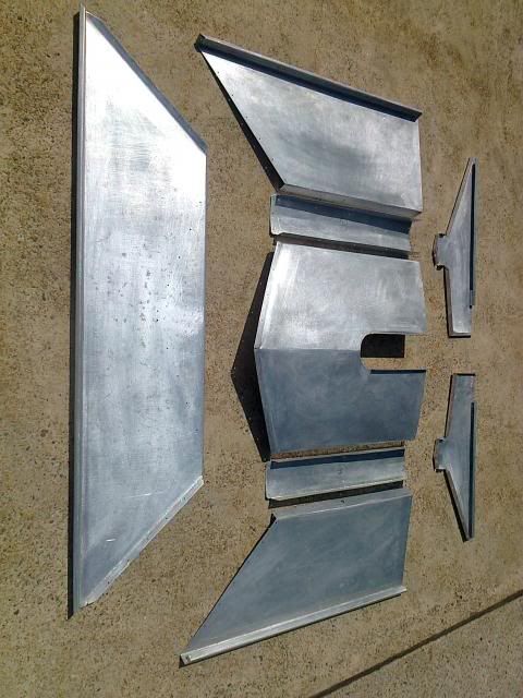
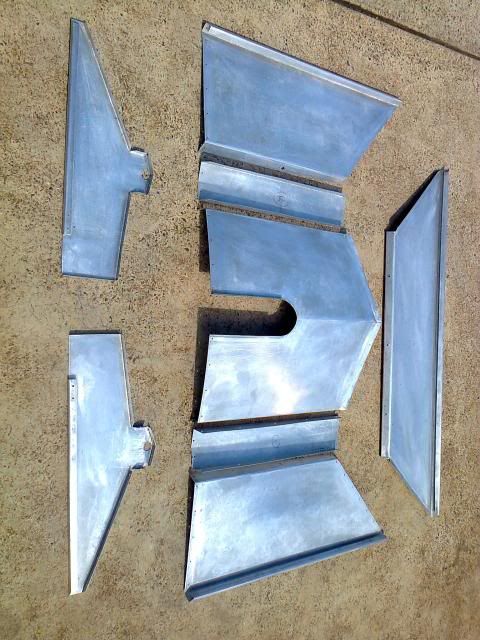
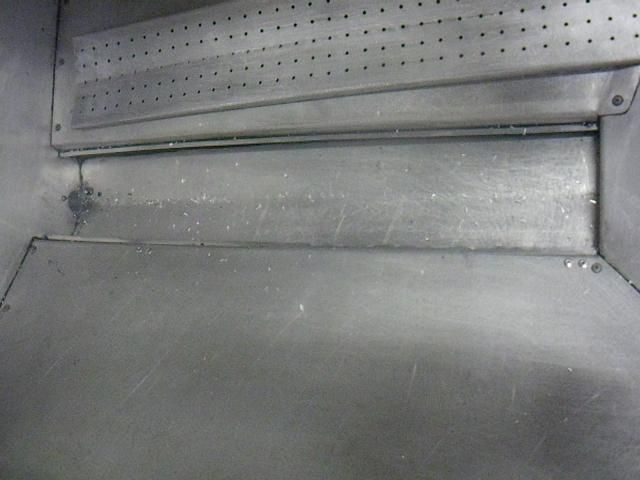
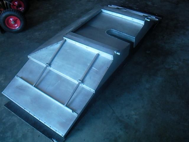
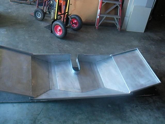
The main tray is 1200mm long x 760 odd wide and 150mm deep. Being 1200mm wide it just fits in my folder and the wings as I call them are 430mm either side which makes it 2 meter over all in length.
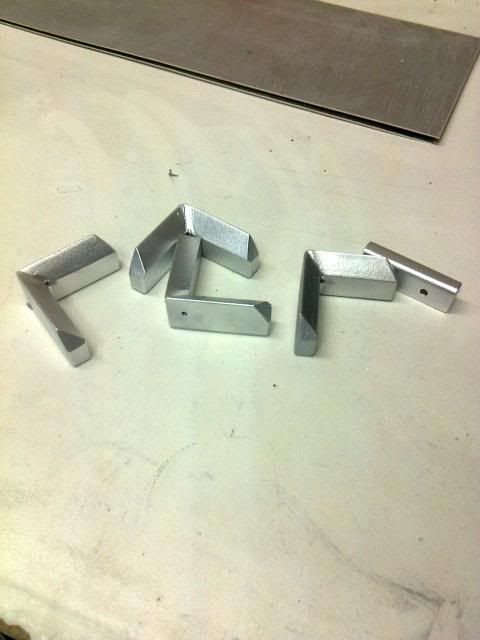
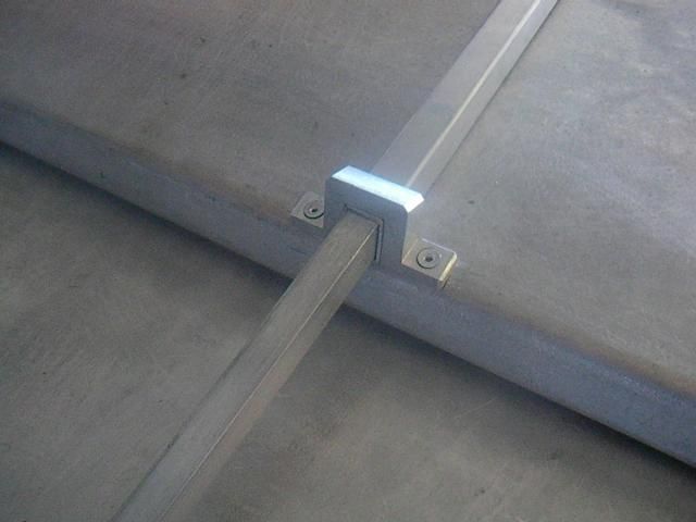
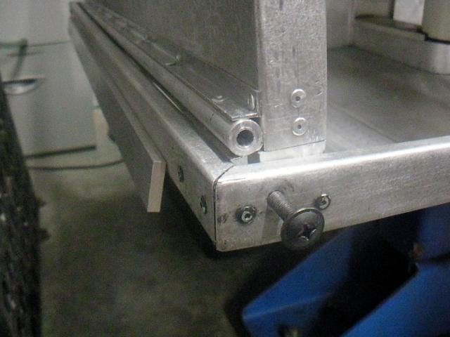
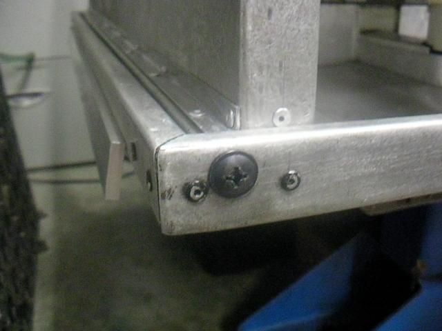
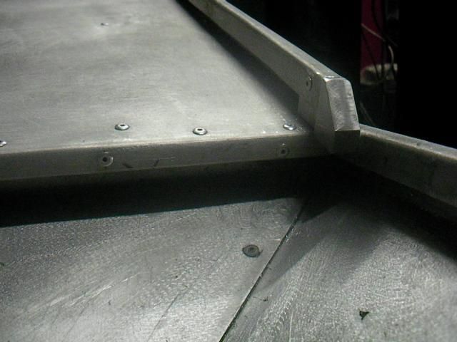
I wanted it all out of aluminum so I can use my magnetic pick up tool as I mainly mill steel, the only steel parts are these corner brackets which hold the main tray corners together, and also the bolts for the wing hinges. I could have went with aluminum but thought steel would be better and they are right on the edge so they should not bother the magnet when cleaning up.
It also had to come off easy and is only held on with 4 x M5 bolts, 2 at the front of the base and 2 on the column.
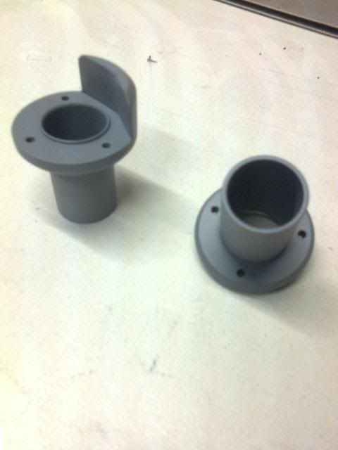
The other single piece is for where it bolts to the column, but had already fitted the other one then remembered to take pictures.
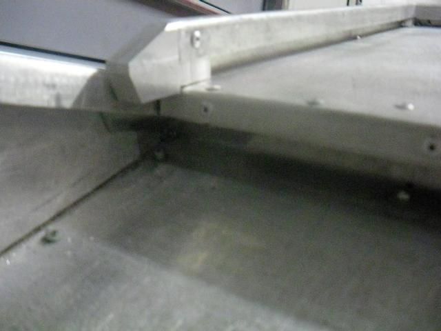
I made the wings because I need to get to the back of the machine to change speeds and maintenance etc, so they are easily folded up out of the way and it also saves room in the shed when it's not in use.
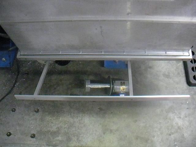
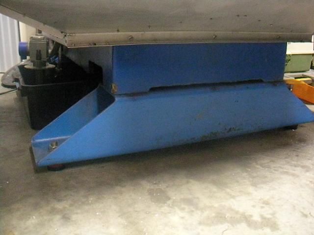
I made the drains either side as the factory tank in the base is a total pain to clean out.
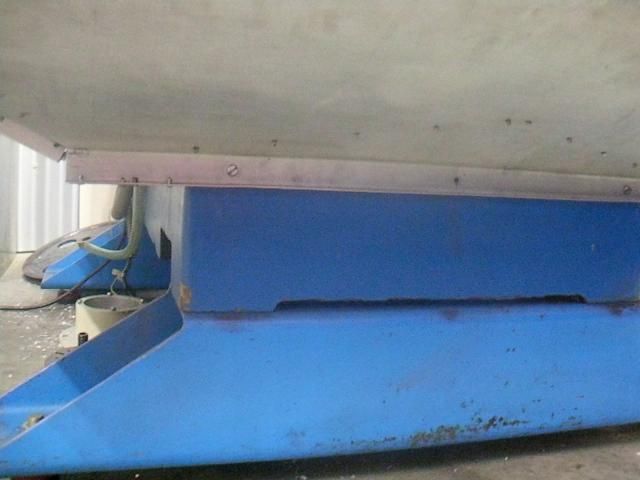
I am going to make an aluminum tank up once I find an old boat tank, but the plastic tub will do for now. The tank fits under the mill base and so will the new tank.

The drain tubes to attach the tubing where just machined out of solid round with the bent flat bar welded on after which suits the shape of the drain.
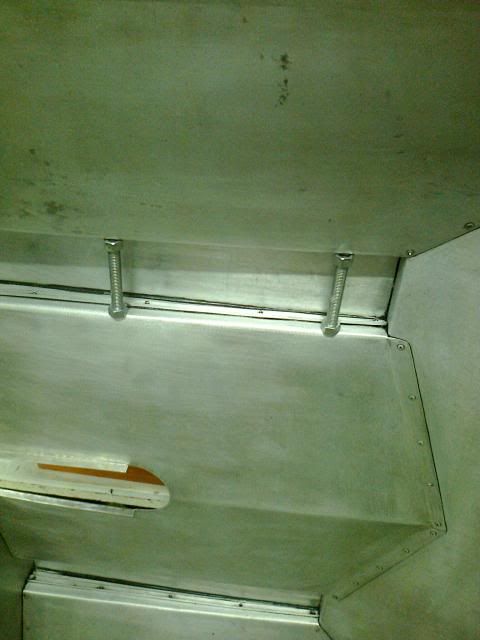
Sealing it all up with the black crap was a mission on it's own, I forget how many rags I went through. In this picture it shows some quick and simple jacking screws to push out while clamps on the other side squeezed in.
The telescopic support is made from 12 and 16mm tube with 25 x 6mm flat bar joining them together. The 6mm flat bar fits perfectly into the 12mm channel which is attached under the wings and it locks them there and saves them sliding back in unless you lift the wing up.
More to come
-
23rd April 2013 04:54 PM # ADSGoogle Adsense Advertisement
-
23rd April 2013, 04:55 PM #2Dave J Guest
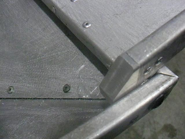
To get the angle to go around the corner I had to cut the aluminum every 15mm and it went around fine, this was all sealed with the black goo like the rest.
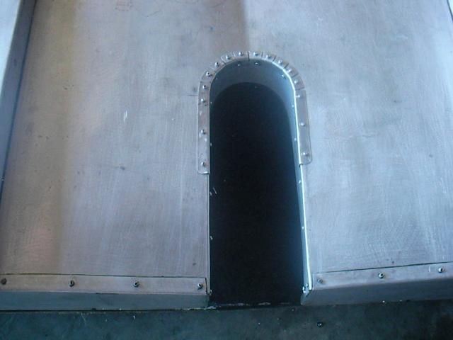
The cap behind the knee screw is just a tight push on fit and has a rubber seal around the screw tube and also at the back where it sits against the column. I was going to fit a vertical piece there as well, but think it will be fine and will see how it goes.
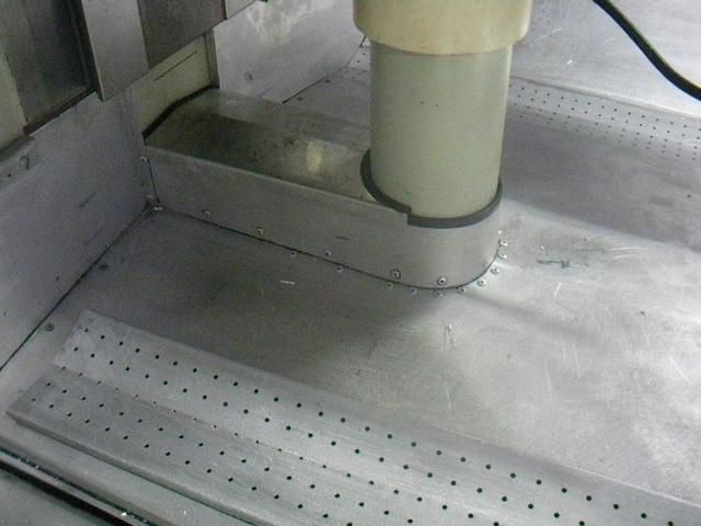
With the drain covers I was going to look for some material online, but just ended up drilling them myself after griding them up at 15mm spacings.
I still need to make a little knob at the front of each one to get them out easy for cleaning.
Just some other random pictures
Dave
Edit,
After reading Rays reply below it reminded me that I need to add some detailed pictures and some more details to the post.
The hinge I used is 1/2 aluminium tube with a press fit solid aluminium rod inside which was drilled out to 6mm to suit the 6mm bolt.
These stops where a pain to make as they where rebated and the back ones needed to be longer and also have the corect angle because of the tray being different at the back.
Dave
-
23rd April 2013, 07:49 PM #3
 GOLD MEMBER

- Join Date
- Aug 2011
- Location
- Melbourne
- Posts
- 2,951
MAN! now thats what I call a coolant tray!
Good to see Dave J engineering is back into full scale production , after a time of turmoil and distraction!
I remember you mentioning a couple of years ago you were going to make a coolant tray out of aluminium so that you could easily use a swarf wand to collect the swarf. I thought that was a top idea!
Looks great Dave.
Simon
-
23rd April 2013, 09:17 PM #4
GOLD MEMBER


- Join Date
- Jun 2008
- Location
- Victoria, Australia
- Age
- 74
- Posts
- 6,132
Hi Dave,
Impressive work, well thought out, with great attention to detail, and clean neat execution.
I've never used flood coolant on the HM52, but seeing your coolant tray I'm tempted, especially when the CNC conversion gets back on track.
I'd be interested to see what you have planned for the new tank and pump arrangement.
Regards
Ray
-
23rd April 2013, 09:47 PM #5
.
- Join Date
- Nov 2008
- Location
- Perth WA
- Age
- 71
- Posts
- 5,650
Nice work Dave.
Bob.
-
23rd April 2013, 09:53 PM #6
Blacksmith, Cabinetmaker, Machinist, Messmaker
- Join Date
- Dec 2011
- Location
- Canberra
- Age
- 40
- Posts
- 4,467
Hi Dave,
Very nice No more puddles on the floor with that one.
Will you be putting an extension on the front of the table to catch the runoff from the vice too? I found that was always the worse with the HM50. The verniers design is a bit better and most of it seems to end up back in the tank.
Have you filled the system yet? I would really recommend going to full synthetic, it doesn't go off or gum up the system like soluble oil does.
Cheers,
Ewan1915 17"x50" LeBlond heavy duty Lathe, 24" Queen city shaper, 1970's G Vernier FV.3.TO Universal Mill, 1958 Blohm HFS 6 surface grinder, 1942 Rivett 715 Lathe, 14"x40" Antrac Lathe, Startrite H225 Bandsaw, 1949 Hercus Camelback Drill press, 1947 Holbrook C10 Lathe.
-
23rd April 2013, 10:21 PM #7
SENIOR MEMBER
- Join Date
- Jun 2004
- Location
- Kyabram. Vic
- Posts
- 826
Have to agree with Ewan re the coolant. I could only get the semi synthetic cutting fluid from a H&F agent around here; or soluable oil. I found that the sol oil kept going off; also caused a skin allergy and stripped machine paint and powder coating.
The semi synthetic has lasted well and much kinder to the machine and myself.
Ken
-
23rd April 2013, 11:49 PM #8Dave J Guest
Thanks for that Simon,
Yeah I am back in the saddle so to speak, and it's good to be back in the shed.
I have another project on the bench which is a taper attachment for the lathe. I just paint stripped it and expected to see rough cast under the putty and need machining, much to my surprise it was nicely machine with no putty only paint there.
I was glad I didn't need to pull the saddle of because I have a big enough job with making a new telescopic screw along with re mounting the light, coolant nozzle and DRO scale reader head mount as none will fit back on in there original place.
Dave
-
24th April 2013, 12:13 AM #9
SENIOR MEMBER
- Join Date
- Sep 2011
- Location
- Ballarat
- Age
- 65
- Posts
- 2,659
Hi Dave,
Gotta say it again, "great to have you back". The boss has just finished a full set of drawings for the taper turning attachment on the little Bantam at work that he is happy to make available to Forum members. He flies out to Cairns for 3 weeks but can be sorted when he gets back if you are interested. He has done them for Peter (PDW) in return for very generous gifts ( I haven't forgotten you Peter).
Oh Yeah, great work on the coolant tray...as usual. You could probably machine the Queen Mary and not lose a drop
Phil
-
24th April 2013, 12:14 AM #10Dave J Guest
Hi Ray,
Thank you for the compliments, I added a few more detailed pictures to the post as you reminded me I left out a few.
The little end stops for the wings to sit at 90 degrees where a pain to make and to tell you the truth I was glad it was finished. Every time I thought I was close I would remember something else and then I ran out of pop rivets and had to wait for them to turn up.
I am not sure how tall you or Josh are but I find the 150mm square tube risers and the feet under it make it a perfect hight when I am standing on the 50mm plastic dangerous goods pallets my mate picked up for me, they are really great for hiding swarf so your not walking in it.
Since the mill has an easy 150mm plus tank it will be that high which matches the pump just nicely and will come out to where my raising blocks are either side.It will also have castor's on it but they will be stepped up so I only lift it up around 10mm off the floor.
It will have the return on one side and the pump on the other with a small wall about 30-50mm high in the middle to stop swarf getting to the pump. I will also have fly screen on the return like my bandsaw to collect plastic and aluminum shavings. The return line from the left will go just nicely through where the fork lift slot is in the base which will give it a nice run to the other side.
Dave
-
24th April 2013, 12:21 AM #11Dave J Guest
Thank Bob and Phil,
Since you replies are pretty much the same I will address you both together.
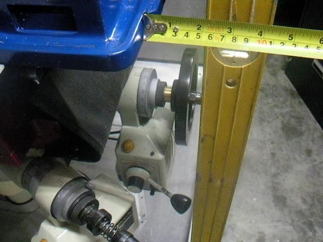
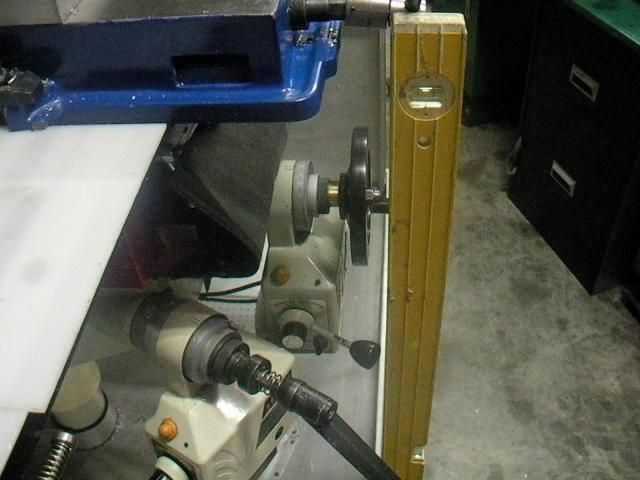
I made the coolant tray up so when the 1 meter table is either way it is cover plus a bit. The table hand wheels just sit inside the tray when at full travel either way which will allow me to cover the extra bit of travel I am yet to get out of it with some mods.
When I am using coolant I find it always wants to run along the table edges, so this has it covered.
I am going to make splash backs off the column and also around the table in preparation for CNCing it.
Dave
-
24th April 2013, 12:34 AM #12Dave J Guest
Hi Ewan, thanks and yes no more puddles on the floor.
I just ducked up the shed for more photos for you.
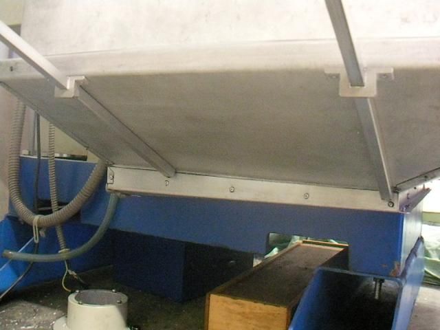
Yep that is a problem with the vise but I have it covered and designed into it.
As you can see from the picture below, with the 280-290mm extension I still have 55mm to the tray edge at the front which is plenty because you are only ever briefly machining out there and the coolant usually runs around the vise channel anyway with it's design like a Kurt vise..
I could have come out further but didn't want to crack my shin on it.
As for coolant I emptied out the mill when I moved it and have full synthetic coolant to go back in, the stuff in it was rank. This also made me make the new coolant tray as cleaning the base was a huge job and I coolant was not going back in after that.
I should have really washed it out on the way in as I could have just used the hose.
Dave
-
24th April 2013, 12:41 AM #13Dave J Guest
Thanks Ken,
 Originally Posted by Toggy

It's funny you mention that, a few months back I cleaned the H&F old coolant out of the mill and the next week or two I started getting these little sores on my hands and a few on my knees. I went to the doctors and got some antibiotics which cleared it up in no time.
I put it down the the old coolant as it sat for 6 months untouched in the mill and it pretty well had pizza's floating on top, and as usual I didn't wear gloves.
Dave
-
24th April 2013, 01:36 AM #14
GOLD MEMBER
- Join Date
- Jul 2010
- Location
- Melbourne
- Posts
- 7,775
Hi Dave,
Nicely done.
Do you have a real folder in your collection?
Is that ball valve in the mills tank factory?
Stuart
-
24th April 2013, 01:45 AM #15Dave J Guest
Hi Stuart, thanks.
It's the folder I have spoken about that I picked up for $10 at a garage sale as they never knew what it was or did. I will snap a few photos tomorrow for you, but it does a good job, though you do get a bit or rounding in the bend in the center. A bit of bracing would fix it, but it's one of those jobs I will get around to.
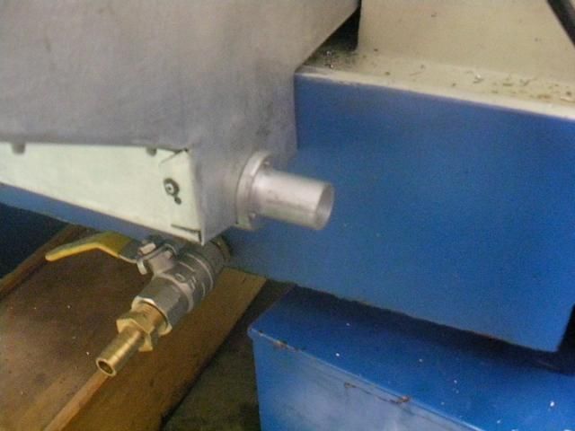
Yes thats a ball valve that needs to come out now. I drilled the base out and taped it for pipe threads at an angle so it made it easier to drain because the little tiny factory hole was useless being around 10mm and only a bung. If a bit of swarf got stuck or anything like it you would then need to put your hand in to unblock it, so your hands where in the crap you where getting rid of.
Dave


Similar Threads
-
Cheap Coolant system for a mini-mill
By Jors in forum METALWORK FORUMReplies: 11Last Post: 25th January 2013, 05:54 AM -
Coolant
By CGroves in forum METALWORK FORUMReplies: 3Last Post: 23rd May 2012, 08:35 PM -
adding coolant to mill
By tanii51 in forum METALWORK FORUMReplies: 4Last Post: 12th November 2010, 12:54 PM -
which coolant ?
By Oldhack in forum METALWORK FORUMReplies: 16Last Post: 1st October 2009, 08:06 AM
 Members who have read this thread: 0
There are no members to list at the moment.