

 Thanks: 0
 Likes: 0
 Needs Pictures: 0
 Picture(s) thanks: 0
Results 16 to 30 of 159
-
5th November 2010, 11:42 PM #16Dave J Guest
 Smart a** Stuart LOL
 Originally Posted by Stustoys

I am sure it will be easy when I know how, but I am still not sure how to do it.
Is it uploaded still to photo bucket? the forum? does it come out full size like the one's I posted above?
Thanks for your time on this DJ
Dave
-
5th November 2010 11:42 PM # ADSGoogle Adsense Advertisement
-
5th November 2010, 11:53 PM #17
 GOLD MEMBER


- Join Date
- Jul 2010
- Location
- Melbourne
- Posts
- 7,775
As this is your thread Dave I guess OT is ok

No photo bucket needed
When you write a post and "manage attachments", once you have uploaded the picture it shows up just above the "manage attachments" button. Right click on it and copy shortcut. press this

button at the top of the post window( on the same line as the bold button), paste the shortcut into the window that pops up.
Done.
Stuart
-
6th November 2010, 12:10 AM #18Dave J Guest
I got it thanks Stuart.
The trouble I was having was I was highlighting it then copying it, instead of the right click.
Dave
-
13th November 2010, 01:18 PM #19
GOLD MEMBER
- Join Date
- Jun 2008
- Location
- Victoria, Australia
- Age
- 74
- Posts
- 6,132
Hi Dave,
Crossing over from the HM52 conversion thread....
Yes, I'm looking to replace the spindle bearings pretty much same as you have done, I haven't checked the amount of thread, but I'd like to see the dimensions of the parts you made.
The bearing spacer at the top of the spline is a nice improvement as well, so I'll do that one as well.
Your work on the HM52 is much appreciated, thanks again.
Regards
Ray
Edit the guy at the bearing place tells me that for the 6009-2RS the "2RS" means 2 rubber seals.. makes sense, what did you end up doing for seals?
Is it just the larger size nut enough or is there another seal?
-
13th November 2010, 02:03 PM #20Dave J Guest
Hi Ray,
You must have missed the bit in the first post about that problem.Your bearing bloke is right about the seals.
"There was also the problem of the taper bearing not having rubber shields like the standard bearing so it would need a cover of some sort.
I thought about it a bit and could see that to get more thread engagement I could make a nut with a extended centre that goes down inside the bearing and be large enough to cover the whole bearing out to the edge of the quill."
With the quill up inside the head it is pretty well protected from dust etc, so as long as there is no grit on the head casting up in their it should be fine.
Will get the nut measurements posted up tomorrow for you as it was just made out of my head to suit.
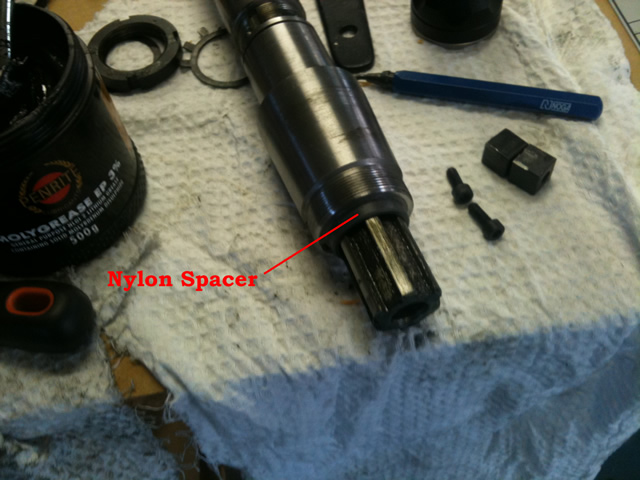
The nylon has quietened it down even more, has anyone else finished theirs, Eskimo, Stuart?
I need to get posting as I found plastic spaces in between the the top bearing pulleys that I replaced, as well as other mods along the way.
With all the new bearing in, my mill runs really quiet now as a belt drive should.
Dave
-
13th November 2010, 05:33 PM #21
GOLD MEMBER
- Join Date
- Jun 2008
- Location
- Victoria, Australia
- Age
- 74
- Posts
- 6,132
Hi Dave,
I pulled down the spindle bearings, to see what I needed to do, and I have an idea that I would like your opinion on.
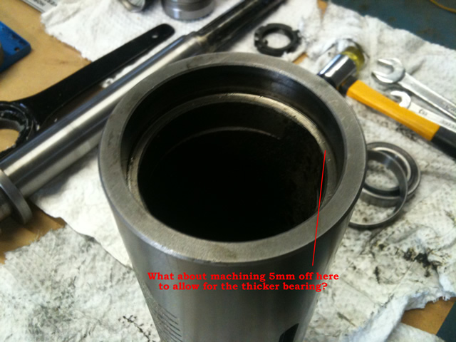
This is the top of the quill, where the spindle bearing goes, If I can get this into the lathe (that's a big if).
What about turning that bearing retaining lip down by a few mm to accommodate the thicker tapered bearing?
Regards
Ray
-
13th November 2010, 06:05 PM #22Dave J Guest
Hi Ray,
It would work just as good but you will still need a large washer or something over the bearing to keep it covered.
I looked at doing mine that way, but the casting in mine tapered out pretty quick and would have only left half the width of bearing seat going down 4mm.
If you do go that way only go down 3mm so the nut/washer covering the bearing can still go close to the outside of the quill. If it only comes to the outer edge of the bearing you could get crap in it between the nut/washer and the inner part of the quill.
I have 2 steadies and it only just fitted in one of them with the fingers right out of their slots (another project larger steady) so I could have just done it in mine.
The inner of the taper bearing is the same height on the bottom so it sits on the spindle the same amount as the original one, it is just the top.
Dave
-
15th November 2010, 11:36 PM #23Dave J Guest
Dimensions for the nut.
Ray have you worked out which way your going?
Dave
-
16th November 2010, 12:46 AM #24
GOLD MEMBER
- Join Date
- Jun 2008
- Location
- Victoria, Australia
- Age
- 74
- Posts
- 6,132
Hi Dave,
I'll make the new nut as per your drawings, the largest bar stock I have is 75mm, but I think I'll just get some 90mm bar stock. Always comes in handy.
I did the plastic spacer earlier tonight.
I'm going to replace the main pulley bearings with "Brand" name bearings while I've got it pulled down.
I've cleaned out all the "chicken fat" and I'm using that Molygrease Lithium stuff, what grease are you using.
Regards
Ray
-
16th November 2010, 01:36 AM #25Dave J Guest
I went through all the bearing places trying to find an answer for grease. I finally found a guy that new what he was talking about,and recommended standard wheel bearing grease or equivalent because it only spins at 3000rpm.
I told him I had been recommended some number HT grease, and he said that it would be no good unless it was to hot to touch by hand.
I see you made the spacer, did you have problems as well with knocking or noises?
You will be happy with the results from it and the new bearings, while your their you may as well do the idler pulley ones as well.
I don't know what your idler pulley is like but mine swivels on the shaft so you don't have to undo the nut to adjust it, the first mill I had I had to undo the nut. It makes belt changes easier as you can pull the pulley either way and when you tighten it it centers itself.
I just made my nut out of plate to save cost, have you seen the price of 90mm bar? Going by Scott's online (a good source for prices) it is $148 mtr
Scott Metals - Products: Bars
Dave
-
16th November 2010, 10:58 PM #26
GOLD MEMBER
- Join Date
- Jun 2008
- Location
- Victoria, Australia
- Age
- 74
- Posts
- 6,132
Hi Dave,
Well, I got the mill back together. There was enough thread to temporarily re-fit the new bearings while I get the new nut made. I managed to get some 100x16 mild steel flat ($14 for 500mm), so I'll cut the new retaining nuts from that.
It sounds nice and smooth, just a gentle whirring noise. But I am seeing a faint vibration, the dial test indicator vibrates (maybe +-0.01mm) when I put it on the quill. Stops vibrating when I tighten the quill lock.
So, I'm about to pull the spindle down again and see if I can find the problem, any ideas what to look for?
Regards
Ray
-
16th November 2010, 11:53 PM #27Dave J Guest
It sounds like the spindle spline is running on the plastic spacer giving you the vibration and then tightening it pulls it into line.
Does pulling the quill down far enough so the spine is out of the plastic spacer stop it?
I am sure you installed it properly but just check the top bearing is sitting square, as with the nut not on all the way maybe kicking it out a bit.
Dave
-
17th November 2010, 12:42 PM #28
GOLD MEMBER
- Join Date
- Jun 2008
- Location
- Victoria, Australia
- Age
- 74
- Posts
- 6,132
Hi Dave, You are right, the vibration is caused by run-out (0.04mm) on the top pulley and Originally Posted by Dave J
that is being transmitted to the unlocked spindle by the plastic spacer. When I drop the quill down past the spacer it all but dissapears, and of course locking the quill stops it completely.
I checked the NSK pulley bearings to make sure they were running true, and they are spot on, so it's the machining on the pulley bearing support.
The spindle runs true with no run-out. That's the main game.
Here's another idea for you to think about, the quill moving when the quill lock is tightened, and I wonder if I could put a bearing running vertically (a bit like a linear bearing) to push the quill back and take up that slack.
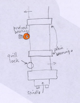
Drawn with the only program I'm "really" comfortable with... and cheap too!
Regards
Ray
-
17th November 2010, 01:27 PM #29Dave J Guest
Hi Ray,
I thought you would have checked the bearings were right.
Did you setup the pulley shaft in the lathe running true with the bearing journals and bore the pulley shaft before fitting the plastic spacer? I did this and put it in my first post as I found a lot of runout in it.
Also when you put the pulley on for the final time, I found that running a dial indicator on the pulley, and trying different positions on the shaft got it running almost perfect.I was going to true the taper shaft up, but being a taper would make the pulley sit lower so this was a compromise.
Did you get your parcel in the post?
Dave
-
17th November 2010, 02:14 PM #30
GOLD MEMBER
- Join Date
- Jun 2008
- Location
- Victoria, Australia
- Age
- 74
- Posts
- 6,132
Hi Dave, Originally Posted by Dave J
Yes, arrived today! Thank you. I'll post that graduated ring in the next few days.
I'll try rotating the pulley to different orientations with respect to the taper. I'll let you know how it goes later tonight.
Regards
Ray


Similar Threads
-
HM52 CNC Conversion
By RayG in forum METALWORK FORUMReplies: 182Last Post: 16th November 2010, 09:03 PM -
HM52 lathe
By Stustoys in forum METALWORK FORUMReplies: 6Last Post: 21st August 2010, 01:39 AM -
Wiring Diagram HM52
By eskimo in forum METALWORK FORUMReplies: 1Last Post: 30th May 2010, 02:15 PM -
S/h hm52
By Dave J in forum METALWORK FORUMReplies: 0Last Post: 23rd April 2010, 06:35 PM
 Members who have read this thread: 0
There are no members to list at the moment.