

 Thanks: 0
 Likes: 0
 Needs Pictures: 0
 Picture(s) thanks: 0
Results 1 to 13 of 13
Thread: Cone clutches and belt drums
-
10th July 2015, 08:04 PM #1
 Philomath in training


- Join Date
- Oct 2011
- Location
- Adelaide
- Age
- 59
- Posts
- 3,149
 Cone clutches and belt drums
The picture below is of a complete J&S 520 workhead drive and that's one of the looming challenges ahead of me. I've been thinking about it for several months and think I have a workable design but would be glad of a few opinions and thoughts on some of the detail that I have not resolved yet.
003 (Medium).JPG
Below is a concept sketch (not up to Bob standards - sorry) that tries to explain what I want to do. The original drive has a lever that will couple and decouple the workhead drive drum to the shaft. The drum is needed as when the bed moves back and forth, so does the workhead and so the belt needs to move with it. Ive never done anything like this and am assuming that because it has been done it can be done again but it's all up in the air at the moment. The drum will be approx 3" in diameter and the shaft is 20mm. Speed is around 400prm
clutch (Large).jpg
Stepping through, from the motor shaft (driven via micro-vee belt to enable speed changes), the workhead shaft is driven. I have a spring loaded cone clutch that can move along the shaft but is keyed to the shaft to stop it rotating (or rather, to fix it so it rotates with the shaft). In it's natural state the cone is pressed into the conical seat in the drum. The reaction force is provided by another block pinned to the shaft at the other end. When engaged, the drum is fixed relative to the shaft and so rotates. When the lever is moved to the right, the cone is removed from it's seat and (at least in theory) the drum can spin on the shaft. In the sketch the green strips are a plain (self lubricating) bearing material.
So -
- Does anyone see any reason it won't work as planned?
- Do I need some bearing material between the drum stop and the drum so that when the clutch is disengaged, there is no tendency to keep driving?
- Should I have a small spring to push the drum out a fraction when disengaged (bearing in mind that only a mm or two would be required, and I may need another stop to prevent the drum being pushed into the cone
- So that I can hold the clutch out, I was going to use a tent peg slot to hold the lever out. A simple ball joint on top of the clevis probably won't work - any other ideas? (I'd prefer the clutch engagement/ disengagement to be a one handed operation)
- I'm suggesting using plain self lube bushes but would I be better with deep groove ball bearings (bit worried about the inner race spinning on the shaft then)?
- Anything else I've forgotten?
MichaelLast edited by Michael G; 10th July 2015 at 09:22 PM. Reason: speed added
-
10th July 2015 08:04 PM # ADSGoogle Adsense Advertisement
- Join Date
- Always
- Location
- Advertising world
- Age
- 2010
- Posts
- Many
-
10th July 2015, 09:19 PM #2
.
- Join Date
- Nov 2008
- Location
- Perth WA
- Age
- 71
- Posts
- 5,650
Michael,
I have just forwarded you an email sent to me by Phillip"Metalman" a few years ago regarding lathe clutches. Might be of interest.
Bob.
-
11th July 2015, 09:03 AM #3
Senior Member
- Join Date
- Mar 2014
- Location
- South of Adelaide
- Posts
- 177
It looks like you have a good concept there. I think that the pulley may drag on the end stop when the clutch is disengaged and in not sure that bearing material will stop it. I've just had a brilliant idea but it needs a drawing to explain it properly, more info to follow.
-
11th July 2015, 09:19 AM #4
Senior Member
- Join Date
- Mar 2014
- Location
- South of Adelaide
- Posts
- 177
modified drawing.jpg
Sorry for defacing your drawing Michael, paint isn't very user friendly.My idea is a brake on the drum so id positively stops when the clutch is disengaged. We have a couple of machines at work that run on when the clutch is disengaged and it is a pain in the a. If you put flange on the drum and have a fixed pad on the frame and a light spring between the stop and the drum it should work ok.
-
11th July 2015, 09:43 AM #5
SENIOR MEMBER
- Join Date
- Aug 2008
- Location
- Adelaide
- Age
- 68
- Posts
- 834
I'm wondering if there would be more drag (and hence tendency to drive the drum whilst the clutch is disengaged) from the plain bush bearings between the shaft and the drum than there would be between the drum and end-stop. Could they be replaced with ball/roller/needle bearings.
You could presumably use a radial thrust bearing between the drum and end-stop if one was available in the size necessary as well.
When you try and disengage the clutch, what happens if the two angled faces are "stuck" together and the drum just follows the drive cone as you move it to the right? the angle of the mating faces will need to be such that you get good drive but also such that they are self-releasing.
-
11th July 2015, 10:03 AM #6
.
- Join Date
- Nov 2008
- Location
- Perth WA
- Age
- 71
- Posts
- 5,650
Michael,
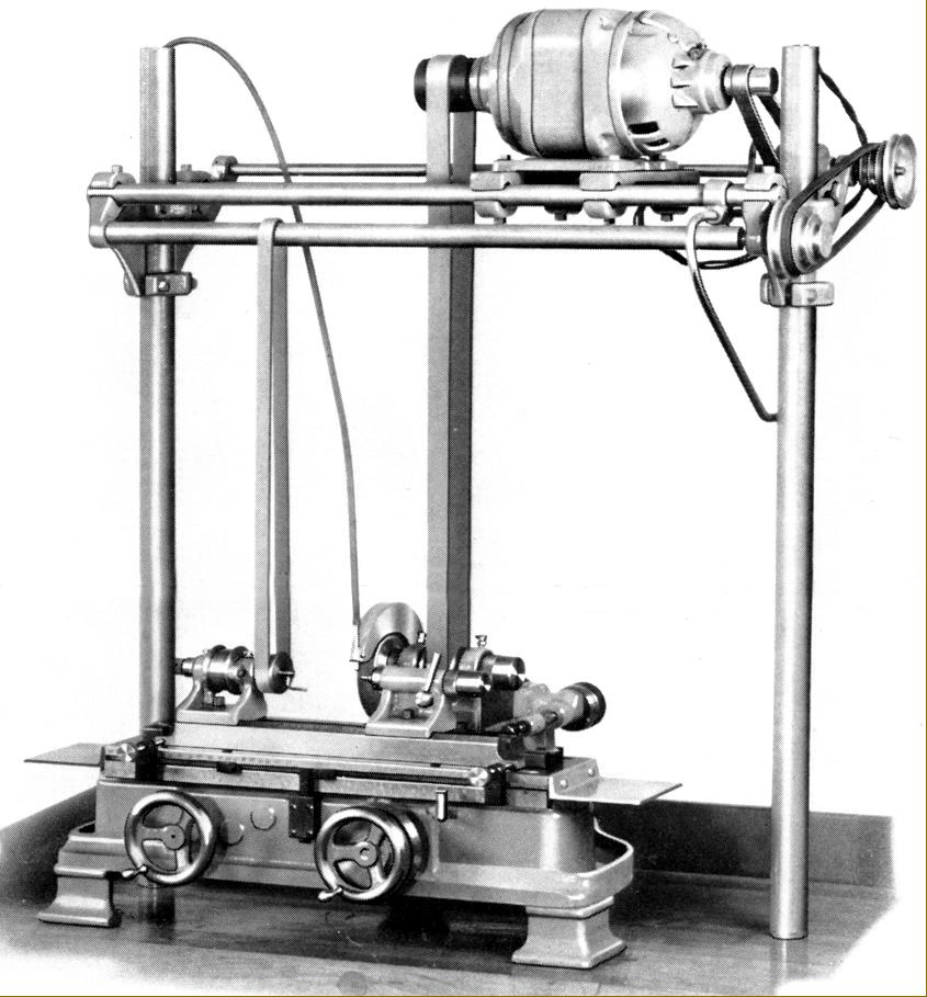
Doesn't the belt from the workhead to the countershaft simply walk along the countershaft pulley or drum, following the movement of the workhead? If it does, why make your pulley slide? Crystal Lake employed a similar but simpler overhead drive on their tabletop grinder where it would appear the belt walked. ( Photo from Tony's site )
Bob.
-
11th July 2015, 10:35 AM #7
Philomath in training
- Join Date
- Oct 2011
- Location
- Adelaide
- Age
- 59
- Posts
- 3,149
The only reason I am allowing some movement laterally (and only a couple of mm) in the the drum is so that it can clear the drum stop. I did think about using fixed bearings but was concerned with the side loading they might experience. Originally Posted by Anorak Bob

Roller and ball bearings were considered but with the exception of sealed deep groove BB's all the other options needed some way of maintaining lubrication. Because the shaft is horizontal potentially that meant I could have oil dripping out the ends (unless I added seals - extra complication). Not sure what the original had but given plain bearings in the wheelhead it would not surprise me if there were plain bearings in the rollers too. There are certainly enough grease nipples. The PTFE/ bronze bushes that you get these days are pretty good as far as friction goes. If I include a brake as per Ash's comments below it won't be a problem if there was a tendency for some slight driving on. Originally Posted by Gavin Newman
As per good grinding practice (or so I'm told) I don't normally intend to switch off the spindle motor (although there is an E stop) while using the machine so having a clutch to enable work to be changed becomes essential.
The cone included angle is around 25 degrees so should self release as the critical number is around 16 degrees
I need to think about that some more. The original does brake when the clutch is disengaged and I like that idea for the very reason you have given. That solution is neat and would do the job. The only issue is space - that edge of the drum is right against the frame and the belt could theoretically travel up there. At one stage I did think of cutting and shutting the frame (it was left unpainted for just that reason!) to move it out but decided to wait and see what else had to be done. Originally Posted by snapatap
Michael
-
11th July 2015, 10:46 AM #8
Philomath in training
- Join Date
- Oct 2011
- Location
- Adelaide
- Age
- 59
- Posts
- 3,149
The Crystal Lake machine is a similar size and it is interesting to see the differences and similarities. I haven't got super powers in this area, but it looks like the table skew has a micrometer head on it. Interesting! I can't recall how the clutch worked on the grinder (read Tony's page some time ago) - I think it just detensioned the belt through an eccentric - that may have caused the same issues with belt run on that have already been noted. Originally Posted by Anorak Bob
Michael
-
11th July 2015, 11:49 AM #9
.
- Join Date
- Nov 2008
- Location
- Perth WA
- Age
- 71
- Posts
- 5,650
There are some detailed photos of the Crystal Lake grinder and its drive here - http://www.lathes.co.uk/crystallake/ Originally Posted by Michael G
-
11th July 2015, 11:56 AM #10
GOLD MEMBER
- Join Date
- Jul 2010
- Location
- Melbourne
- Posts
- 7,775
Is there clearance for the brake to run against the right hand side of the drum? No need for the flange then
-
11th July 2015, 07:17 PM #11
Philomath in training
- Join Date
- Oct 2011
- Location
- Adelaide
- Age
- 59
- Posts
- 3,149
Technically yes, but as that is also the end that has the clutch mechanism (also pending design) I would prefer not to take up real estate at that end if I could. Putting it at the LH end is not a problem - I just have to extend the frame and put in a longer shafts. Originally Posted by Stustoys
Michael
-
26th July 2015, 11:12 PM #12
Member
- Join Date
- Jul 2014
- Location
- Alphen aan den Rijn, Netherlands
- Posts
- 67
I am quite late to read this thread and am reluctant to reply, but when I saw your sketch it reminded me of the working of the clutch/brake of my shaper. I have no experience designing these things, but include the original drawing hoping it is of some use to you.

A is the brake cone and B is the clutch cone. Both are pinned to a common axle and moved left/right with mechanism 5/6. (there is a lever attached to this to manually engage/disengage/brake)
Actually the clutch moves on a key and the drive pulley freewheels until part 3 -which is pinned on the axle with the brake- moves the clutch in to the pulley through part 4 and thus drives the axle with gear 1.
I hope you understand my explanation and find some use for it.
If you would like me to explain more, please let me know.
Peter
-
27th July 2015, 07:59 AM #13
Philomath in training
- Join Date
- Oct 2011
- Location
- Adelaide
- Age
- 59
- Posts
- 3,149
Thanks - it's all contributing to the evolving design.
Michael


Similar Threads
-
Anyone changed a belt on a Woodfast 280 lather - rear door belt change model
By WaggaSteve in forum WOODTURNING - GENERALReplies: 1Last Post: 21st May 2015, 01:25 AM -
mini-cyclone cone - Traffic cone?
By Earthwhile in forum DUST EXTRACTIONReplies: 14Last Post: 21st August 2010, 09:08 AM -
Sawtooth clutches- made any more?
By nswnotill in forum METALWORK FORUMReplies: 11Last Post: 31st July 2007, 09:33 AM -
drills and clutches
By robatman in forum HAND TOOLS - POWEREDReplies: 3Last Post: 28th August 2006, 12:30 AM
