

 Thanks: 0
 Likes: 0
 Needs Pictures: 0
 Picture(s) thanks: 0
Results 1 to 14 of 14
Thread: cylindrical grinding on a TCG
-
24th August 2014, 11:22 PM #1
 Senior Member


- Join Date
- Feb 2013
- Location
- Laidley, SE Qld
- Posts
- 368
 cylindrical grinding on a TCG
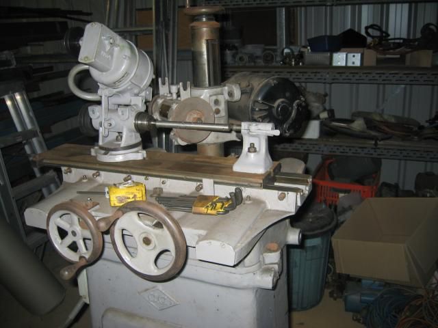
I need to reduce 200mm of 16mm 1020 to .621". I'm thinking that this could be a good first job for my CC Engineering TCG but I have a few questions of those experienced with a TCG.
1. I've done a dummy set up, it seems the only way I can get 200mm travel is to turn the grinding wheel at an angle to the work. Is that an approved/ normal practice?
2. The present work holding arrangement consists of a point on the drive end and a spring loaded point at the tail stock end. Is that sufficient/usual to keep the work turing against the wheel?
3. No guard on the wheel and it doesn't look like there ever was a guard. Is that a feature from times when men were men etc or is it normal procedure for TCGs?
-
24th August 2014 11:22 PM # ADSGoogle Adsense Advertisement
- Join Date
- Always
- Location
- Advertising world
- Posts
- Many
-
24th August 2014, 11:46 PM #2
GOLD MEMBER
- Join Date
- Jul 2010
- Location
- Melbourne
- Posts
- 7,775
Hi Bob,
Something looks strange. Why do you need the angle? Something is fouling between the wheel head and the work head?
Is there any chance the motor is up side down so the wheel is mounted on the wrong side of the spindle?
Stuart
p.s. re guards........ If I recall correctly there is sort of a 1/4 guard mounted from the U's above the spindle. I might have some pictures some where or maybe they are in the thread about my CC
-
25th August 2014, 07:50 AM #3
Pink 10EE owner
- Join Date
- Aug 2008
- Location
- near Rockhampton
- Posts
- 4,304
 Originally Posted by bob ward

I have seen somewhere that running the wheelhead at an angle is common CNC cylindrical grinder practice. It is so the grinder can do straight and then grind a shoulder square at the same time. The wheel is dressed appropriately..Light red, the colour of choice for the discerning man.
-
25th August 2014, 10:21 AM #4
GOLD MEMBER
- Join Date
- Jul 2010
- Location
- Melbourne
- Posts
- 7,775
You might find something useful in this thread if you haven't seen it already
https://www.woodworkforums.com/f65/grinder-140000
Stuart
-
25th August 2014, 08:53 PM #5
SENIOR MEMBER
- Join Date
- Oct 2007
- Location
- Sydney
- Posts
- 2,340
Bob please let us know how you get on with this regarding finish. I'm considering setting mine up for cylindrical grinding, but have heard various reports about expected finish.
With regard the the wheel guard, I can't generalise, and know nothing about yours, but yes my Clarkson has wheel guards (indeed an extraction system). I've never personally had a wheel explode (touch wood) but I've spoken with people who have and apparently it's a time when ones undies disappear up places where they were never intended to go, and visa versa. I'm not sure how much good they do in these situations, but I personally always use guards on grinders.
-
26th August 2014, 02:23 AM #6
Intermediate Member
- Join Date
- Apr 2013
- Location
- San Diego
- Posts
- 31
From your earlier posting.
Gene
-
27th August 2014, 09:31 AM #7
SENIOR MEMBER
- Join Date
- Oct 2001
- Location
- ACT
- Posts
- 455
Think you will need a drive dog on the bar as a point is not going to be enough to drive it properly. No probs with the wheel at an angle but you will need to dress a the wheel so you have a 'flat' in contact with the bar when grinding. Nothing stopping you using it without a wheel guard but may be a good idea to get one at some point.
-
27th August 2014, 11:20 AM #8
GOLD MEMBER

- Join Date
- Aug 2011
- Location
- Melbourne
- Posts
- 2,951
Hi all,
Finding this thread interesting and indeed I will be keen to see what surface finishes can be achieved. I have a question regarding the rotation/direction of the grinding wheel wrt the workpiece. One would assume (yes dangerous) that both grinding wheel and workpiece would need to rotate in the same direction (as opposed to an analogy with 2 gears which travel in opposite directions) otherwise you can get a situation where the surface speed of the grinding wheel could be reduced to near zero. Is this assumption correct? What speed range would you rotate the workpiece, I assume it does not need to be as fast as the grinding wheel, is it too dictated by the diameter and surface speed?
Cheers,
SimonGirl, I don't wanna know about your mild-mannered alter ego or anything like that." I mean, you tell me you're, uh, super-mega-ultra-lightning babe? That's all right with me. I'm good. I'm good.
-
27th August 2014, 12:14 PM #9
GOLD MEMBER
- Join Date
- Jul 2010
- Location
- Melbourne
- Posts
- 7,775
Hi Simon
Well they do......do they need to? well people try all sorts of things when they are after a mirror Originally Posted by simonl

You'd need a large work piece and/or a very fast work head to get close to zero..... I'm not sure I'd want to be around, but if you managed it, you'd likely end up with high speed crush dresser. Originally Posted by simonl
Must say I dont have a number on that....I'll make a WAG at around 200rpm. But I've only used grinders around the size of BT's... maybe bigger ones go slower? Originally Posted by simonl
Stuart
-
27th August 2014, 12:45 PM #10
Senior Member
- Join Date
- Feb 2013
- Location
- Laidley, SE Qld
- Posts
- 368
If I'm reading correctly the data plate on the geared motor that rotates the workpiece, the output speed is 145RPM. Then there are 2 pulley options between that motor and the work piece to give final drives of roughly either 100 or 300 RPM.
-
27th August 2014, 03:00 PM #11
GOLD MEMBER
- Join Date
- Jul 2010
- Location
- Melbourne
- Posts
- 7,775
Originally Posted by Stustoys
Do I get a point for that? lol Originally Posted by bob ward
Hi Bob,
I'm still not seeing the problem. As pictured you have enough left travel to grind to the tailstock end? Shouldn't you have heaps of travel to the right? So is it a Y issue
Stuart
-
27th August 2014, 03:44 PM #12
SENIOR MEMBER
- Join Date
- Jul 2011
- Location
- Melbourne Australia
- Posts
- 1,128
Plenty of manual production grinders had the wheel head slide mounted at a 30 degree in-feed angle.You know how the sine of 30 deg is 0.5. That way it would take off the same amount off the face as it did on the diameter. Originally Posted by .RC.
They used to be very common in the auto industry, for grinding things like pinions and gears. Anything with a shoulder that needed to be true to the journal.
Regards Phil
-
27th August 2014, 08:48 PM #13
GOLD MEMBER
- Join Date
- Aug 2011
- Location
- Melbourne
- Posts
- 2,951
Yes, I'll give you a 100 points for that! Originally Posted by Stustoys
SimonGirl, I don't wanna know about your mild-mannered alter ego or anything like that." I mean, you tell me you're, uh, super-mega-ultra-lightning babe? That's all right with me. I'm good. I'm good.
-
3rd September 2014, 11:24 AM #14
Member
- Join Date
- Aug 2012
- Location
- Adelaide Hills, SA
- Posts
- 87
Other options
Can you swap the tailstock and workhead around? That would place the drive for the workhead away from the grinding wheel and then not need the angle on the grinding wheel? It would look from the pic as though it would work better. You should be able to reverse the direction of the rotation of the workhead either electrically or mechanically.
There is a bracket to hang a gaurd on top of the grinding head, the U shaped brackets. I would spend the time making a gaurd, otherwise you may end up with a saw head!
If you use the setup as pictured I would check that the wheel you select can accept the side load from ginding on an angle. I have only seen it done with saucer shaped wheels on a T&C.


Similar Threads
-
No9 Cylindrical Grinder
By neddyo in forum THE HERCUS AREAReplies: 8Last Post: 27th August 2015, 08:19 AM -
Cylindrical Square
By RayG in forum METALWORK FORUMReplies: 131Last Post: 15th November 2011, 03:18 PM -
New toy TOS cylindrical grinder
By aussiejoeblow in forum METALWORK FORUMReplies: 4Last Post: 18th June 2011, 09:36 PM -
Which Grinding Wheel For Grinding Tungsten Electrodes
By Metal Head in forum WELDINGReplies: 14Last Post: 8th August 2009, 02:23 PM -
Cylindrical cabinet
By 3 toed sloth in forum WOODWORK - GENERALReplies: 19Last Post: 2nd January 2009, 02:35 PM
