

 Thanks: 0
 Likes: 0
 Needs Pictures: 0
 Picture(s) thanks: 0
Results 1 to 15 of 74
Thread: Hafco 960b querys.
-
2nd August 2010, 02:43 AM #1
 Awaiting Email Confirmation


- Join Date
- Jul 2010
- Location
- perth
- Posts
- 268
 Hafco 960b querys.
Hi, have a few queries about a hafco 960b lathe in which i have just set up.
Removed a small 3 cm squared block of steel which clamped the saddle to the bed, should this be removed as i assume it was to lock the saddle during transport?
ran the lathe for a short time, the oil in the inspection window was as clear as water, while running i could see it slowly turning a light shade of brown, the lathe sounds much rougher and louder than another 960b lathe run in the shop, worried there may be rust on the bearings as it was manufactured a year ago.
Would like to empty the gearbox oil, and probably inspect the gearbox by taking its cover off.
There is a rubber plug with oil written on it just above the lead screw on the gearbox, is this the oil drain plug ?
Had mentioned in a previous topic that the lathe was sitting on its gearbox lid as the pallet board was broken, do any other 960b owners know if the lower bolt is a double end threaded black steel with a nut tightened on the gearbox ? this does not look right to me as i can clearly see the impression of a missing washer in the paintwork, where as the upper gearbox cover bolt looks genuine and is the in the same silver finish as the hand wheels.
my guess is the lower bolt broke.
Cannot change to the lower gears, it is impossible to get the belt on to the inner pulleys.
The motor has limited upwards movement, the top of the fan cover end of the motor hits allan bolts that seem to be sticking out about 1 cm, unsure what there purpose is as their not completely bolted in, but are tight, there are 3 allen head bolts that just sit horizontally, above and to the right of the motor on the gearbox, the center bolt is correctly tightened all the way to its head, while the other 2 are not, is this normal ?
do i need to purchase a separate belt for the lower gears ?
supplied a pic of the allen bolts that extend out
planning on making a bracket to hold a light and coolant hose on the cross slide, noticed 2 allen screws on the top far end of the cross slide, can these be used to bolt a bracket to ?Last edited by lather; 2nd August 2010 at 02:45 AM. Reason: double pics
-
2nd August 2010 02:43 AM # ADSGoogle Adsense Advertisement
- Join Date
- Always
- Location
- Advertising world
- Posts
- Many
-
2nd August 2010, 10:54 AM #2
SENIOR MEMBER
- Join Date
- Aug 2008
- Location
- Adelaide
- Age
- 68
- Posts
- 834
That block of steel (at the right hand side of the carriage) is the saddle lock. It's designed to be left loose in normal operation and then clamped up tight when facing off and parting off to stop the carriage moving. I made a threaded tommy bar to make it more convenient to use. From memory it's a 7/16 UNC thread. If it helps I'll take photos and post - let me know.
If you are worried about the gearbox it may be worth draining the oil and refilling, the drain plug is on the left hand end of the gearbox case under the end cover.
The rubber plug you describe is the oiling port for the quick change gearbox (aka the threading gearbox) on the front of the lathe. This leads to a tray which has a number of holes that drip oil onto the gears - this is a total loss system unlike the main gearbox. The idea is that you squirt hydraulic oil into this area occasionally when you are using the QC gearbox - don't worry that it drips out into the swarf tray, that's normal.
Regarding the gear noise, it may be that the unit in the shop was running without the quick change box being driven, normally you leave the QC gearbox out of mesh unless using the threading or power feed modes. The QC box is brought into play via the round knob at the left just underneath the main speed change levers.
If you are running the lathe at high speed you shouldn't run the QC gearbox in the higher gears (ie at the A end of the first sectiony). Generally I leave the QC box in D or E when I'm power feeding. Obviously you use all QC positions when threading but you don't thread at high spindle speeds. The QC box is very noisy (they are straight cut gears after all) if you leave it in a higher gear and run the lathe at fast speeds - scared me witless the first (and only) time I did that!
Also, looking at your photos it doesn't look like you have any grease on the gear-train, this will generate noise as well.
Changing the belt is slightly difficult with the standard belt, I had to take the 127/120 change wheel off to get the belt off the pulley and loosen the splash back to move the motor. The fan shroud was hitting the splash-back so I had to move that temporarily while moving the motor. I bought a replacement belt from CBC Bearings that was very slightly longer and that resolved the issue re the splash back but not the requirement to take the idler gear off each time - I generally just leave the belt in the lower speed position most of the time.
The lower (and upper) gearbox cover mountings on my lathe are as you describe, a double ended stud with a nut locking it to the gearbox casing. I can post photos if you want.
The socket head cap screws at the far end of the cross slide are there for an optional taper turning attachment, they serve no purpose unless that attachment is used so you can use them to bolt your fittings to. I use them the hold my oiling system. I'd be leery of bolting anything with too much weight using them though - I'd be inclined to mount the light on the spash-back and use the cross-slide bolts for the coolant/oiling system.
Those bolts in the picture you refer to are part of the method of aligning the headstock to the ways - don't mess with them!
If you are in any doubt about the oil and/or any damage you should talk to the supplier asap as it will still be under warranty.
Rgds - Gavin
-
2nd August 2010, 12:12 PM #3
GOLD MEMBER
- Join Date
- Jul 2010
- Location
- Melbourne
- Posts
- 7,775
As far as the noise goes. Did you have the cover off the left hand side? On my lathe this cover can rub against the pulley if not in just right spot. Also is the power feed gear in neutral? (it appears to be in your picture of moving the lathe in your other thread) as Gavin says those gears make lots of noise even when adjusted properly, even more it adjusted to tight.(the ones on my lathe can out of line and on and angle, but i have the Chinese one)
Stuart
-
3rd August 2010, 01:17 AM #4
Awaiting Email Confirmation
- Join Date
- Jul 2010
- Location
- perth
- Posts
- 268
thanks for the replies.
managed to change the belt to low speed.
cant understand why the belt isn't at least 1 cm longer, there is plenty of adjustment on the motor bracket for a slightly larger belt.
managed to fit the chuck, thought this would be an easy job, could not get the cam locks anywhere near between the center of the arrow marks, (more like half way between the start mark and the first arrow when turning clockwise), If i loosened the cam lock stud 1 turn there was no locking pressure, called H&F, the service person said not to worry just as long as its tight.
thought this doesn't seem to be properly locked.
Decided to sand the cam-lock studs radius, as the surface looked rough, used a pipe with a similar radius and wet and dry 400 grit paper.
worked well on 2 of these studs first pop, though the 3rd wouldn't line up between the 2 arrow marks after 10 attempts ( after each attempt there was some new scored marks on the cam lock stud, there must be a lip on the inner cam, can these cams be pulled out ? ).
removed a stud from the 4 jaw chuck plate, this worked perfectly as it was.
The other problem is the chuck itself was rough and locking up while tightening or loosening.
took the jaws out and flooded the chuck with oil,its a little smoother but still locks up in certain positions, is this normal or could it be full of contamination.
wasted over 4 hours just to get a chuck in.
Stuart, ran it with and without the cover, plus gave it a short run with the gears disconnected, could be louder, due to the cabinet.
May need to hand turn the chuck of a 960b demo in store to compare the feel.
-
3rd August 2010, 02:14 AM #5Dave J Guest
The cam lock studs come out easy, just undo the allen head bolt holding them in which is next to each cam lock.
A picture of the cam lock is below. You can see were I had to move the detent hole over because one of the cam locks wouldn't line up when open.
What I have found with these Chinese chucks is they have burrs along the slot for the jaw. Take the jaw out and use a fine file to remove them.
Do all H&F lathes come with a total loss oil system in the thread gear box? Mine runs in a bath of oil with a sight glass on the side.
Dave
-
3rd August 2010, 08:23 AM #6
SENIOR MEMBER
- Join Date
- Aug 2008
- Location
- Adelaide
- Age
- 68
- Posts
- 834
See comments in red. Originally Posted by lather

-
3rd August 2010, 12:56 PM #7Dave J Guest
I forgot to put in earlier about the cam studs.
On one of my face plates or chucks, I remember I had to move the studs to different holes to get it to line up between the marks. This is because the threads in each hole and stud start at a different place which in turn gives them a different height when lined up at each full turn.
The pitch on these studs is 1mm and some only needed 0.5mm in height difference to get them to line up.
Dave
-
3rd August 2010, 01:42 PM #8
GOLD MEMBER
- Join Date
- Jul 2010
- Location
- Melbourne
- Posts
- 7,775
Lather,a couple of things you can try on your camlocks, on the 3 jaw swap the worst two pins and see if this helps. If this doesnt help, mount the 4 jaw chuck and check which pin is the worse in that, swap that pin for the worse pin in the 3 jaw. You should be able to get the arrow between the lines.. thats what the lines are there for.
It maybe not be the pins, on my faceplate the camlocks have to be pulled up slowly, a little on each. If you do one up then move the the others you can't do them up. I believe this is because the taper in the faceplate isnt correct.(one of these days I'll start a thread about that)
Stuart
-
3rd August 2010, 02:27 PM #9Dave J Guest
Hi Stuart,
I wrote this up previously in another thread
If your having trouble with the chuck it might be with the taper. Check to see if there is a gap between the two flat mating surfaces of the spindle nose and the backplate.
I picked up a spare D14 mount chuck and found the taper was slightly smaller so it was rocking on my lathes D14 locating taper depending which cam lock you tightened.
I ended up mounting the new 4 jaw back wards into my original 4 jaw and taking a very small cut off the taper then remove the whole lot turn it around and try it. The last little bit was taken off with emery cloth. It took a few goes and but it is fine now and runs true.
Dave
-
3rd August 2010, 02:41 PM #10
GOLD MEMBER
- Join Date
- Jul 2010
- Location
- Melbourne
- Posts
- 7,775
Sorry I missed it if it was in answer to me Dave.
Yes I think that is the problem. I'm just worried that its a little beyond my turning skills just yet. Holding it could be a problem also. But knowing that it's been done before makes me a little happier about trying it.
I'd been thinking for ages "why do they bother on face plates and 4 jaw chucks anyway?" I guess its more about being sure the chuck wont move when working than having the faceplate line up exactly each time.
Thanks
Stuart
-
3rd August 2010, 04:24 PM #11Dave J Guest
Hi Stuart,
No I wrote that up on a thread that Dingo Dog had started, here is the link
https://www.woodworkforums.com/f65/th...chucks-114404/
It just saved me rewriting it all.
You are right, the D1-4 mount is made for good repeatability when reinstalling chucks, face plates or anything else. Were the taper comes in with the 4 jaw chucks and face plates is to keep them central that way they are balanced.
They are not perfect, sometimes when I am setting up for a precision job I find tightening up different cam locks makes a difference.
It is also a good idea to rotate the chuck on the cam locks until you find the most accurate mounting position, then mark the spindle and the chuck or back plate so it can always be mounted back on the same.
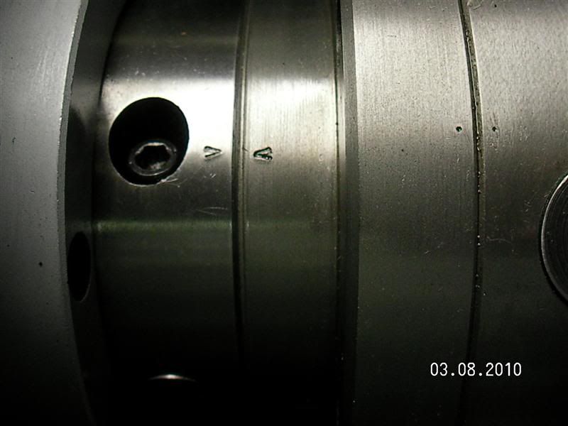
Below is a picture of my spindle, you can see I used the V out of my letter punch set to mark it. You can also see the 2 centre punch marks on the back plate and chuck were the chuck runs the best on the back plate.
Dave
-
4th August 2010, 12:13 AM #12
Awaiting Email Confirmation
- Join Date
- Jul 2010
- Location
- perth
- Posts
- 268
the fitting of the chuck looks fine, the main concern i had was the reply by H&F that it doesn't matter if its not between the arrows, i didn't believe it so
did a little sanding on the cam lock studs radius.
Last thing i wanted was a chuck flying off.
had tried different cam lock positions in which 2 had come near the arrow and the 3rd about half way between the straight start mark and the first arrow.
had marked this position when repeatedly sanding the stubborn cam stud.
When replacing this stud with 1 off the 4 jaw chuck , it worked perfectly, so I'd say the machining isn't accurate, i assumed this was all tested before
purchase.
Dave j, thanks for the cam lock pics, will pull out the cam locks as it looks like 1 has a slight burr.
hope the burr doesn't interfere when pulling it out.
Will be taking back the chuck, forgot to mention- it gets tight without the jaws in the chuck, i can see this being a pain when using,
Are chucks meant to be fairly smooth, easy 1 handed operation when adjusting the jaws, when it locks i need to use both hands on the key with a little strain to get it to work ? its very jerky with or without the jaws.
expecting to be told its normal when i return the chuck.
Need to check if the 4 jaw has the same problem before returning the 3 jaw.
its a little more work than i thought when setting up a lathe.
-
4th August 2010, 01:59 AM #13Dave J Guest
That chuck sounds like the scroll is binding, it should turn easy with the jaws out. It's not your problem to fix it since it's under warranty, I would take it back to H&F.
Dave
PS
PM sent
-
4th August 2010, 08:47 AM #14
SENIOR MEMBER
- Join Date
- Aug 2008
- Location
- Adelaide
- Age
- 68
- Posts
- 834
You definitely should not have to force the scroll, as Dave says - take it back and get it replaced. You seem to have been unlucky with your chuck(s), mine were fine straight off with no fettling required. Originally Posted by lather
I assume you were supplied with Fuerda chucks, these are good chinese chucks but being chinese the quality is likely to be variable. I was surprised that H&F supplied chinese chucks on the taiwanese made lathe but I was told that it was a cost thing.
-
4th August 2010, 06:52 PM #15Dave J Guest
Hi,
The quality and the parts vary on the Fuedra Chinese chucks.
Here is one story
The 250mm chuck I bought from H&F had one jaw that never even touched the screw.
I tried the jaw in my 200mm chuck and found it fitted, so it came with 3 x 250mm jaws and one 200mm jaw.
They took the chuck back then gave me a new one but it cost me $50 in fuel for the trip. While I was there I checked the jaws in the new chuck and they were fine.
After getting it out at home to use it, I found the safety chuck key was to big for the chuck You cant win them all. I never bothered going back again, I just threw it in the cupboard and used the one off my other 4 jaw chuck, one day I will get around to milling it down.
Both of these chuck boxes had been opened before I got them.
Dave


Similar Threads
-
safe lifting points of hafco 960b lathe
By lather in forum METALWORK FORUMReplies: 35Last Post: 16th August 2010, 01:29 AM -
cutting 3.5mm on 960b lathe with imperial leadscrew
By B the B in forum METALWORK FORUMReplies: 16Last Post: 25th June 2010, 01:28 AM -
Who has either a Hafco AL-336, AL-960B or AL-340A
By steran50 in forum METALWORK FORUMReplies: 40Last Post: 7th June 2010, 10:23 PM -
HAFCO AL-960B vs Myford Super 7
By DustInOz in forum METALWORK FORUMReplies: 3Last Post: 8th May 2010, 10:51 PM -
AL-330L vs AL-960B
By Sterob in forum METALWORK FORUMReplies: 1Last Post: 22nd February 2007, 09:55 PM
