

 Thanks:
  Likes:
  Needs Pictures: 0
 Picture(s) thanks: 0
Results 1 to 15 of 49
Thread: Anyone heard of RSB??
-
24th February 2014, 10:20 AM #1
 GOLD MEMBER


- Join Date
- Dec 2007
- Location
- Melbourne
- Posts
- 3,277
 Anyone heard of RSB??
Just picked up this gal and can't seem to find any info what so ever on her. IMG_4889a.jpg
Nor can I find one of the same design. Most are an upside down L shape not F shape like this or they have the Y shape with the pulleys running horizontal across the top.
It is also an unusual size from the others I have seen are much smaller or huge at full size.
It has been modified with a motor mount added and the belt drive changed to a VEE pulley.
It is has RSB embossed in the casting IMG_4890a.jpgand was probably imported into Australia and retailed by Miller & Co (Machinery) Pty Ltd Machinery Specialists South Melbourne & Bendigo as per the brass plaque.
Looking for any info related to either of these companies which may help in identifying the drill with the intention of getting it back to original state.
Is there anyone into these types of drill??
Sometimes referred to as Camel Back Drill, Sensitive Drill, and Hunch Back Drill.�..Live a Quiet Life & Work with your Hands
-
24th February 2014 10:20 AM # ADSGoogle Adsense Advertisement
- Join Date
- Always
- Location
- Advertising world
- Posts
- Many
-
24th February 2014, 12:19 PM #2
Senior Member
- Join Date
- Mar 2009
- Location
- Melbourne
- Age
- 54
- Posts
- 380
What a little ripper, outstanding score.
There is an RSB lathe on lathes.co.uk. The logo looks the same as the one on your drill.
http://www.lathes.co.uk/rsb/
Sorry I cant add any more info but I did manage to find a photo of Miller & Co.'s South Melbourne premises from 1938 on the Museum Victoria website.
http://museumvictoria.com.au/collect...-victoria-1934
Cheers,
Greg.
-
24th February 2014, 03:05 PM #3
GOLD MEMBER
- Join Date
- Dec 2007
- Location
- Melbourne
- Posts
- 3,277
 Originally Posted by kwijibo99

Greg,
That is great info�. I now at least know it came from the UK.
Looking similar to the well-known "Relm" lathes, the RSB might have been made by Breeds, in Leeds, a company with a connection to Relm and whose lathes were sometimes branded "Atlas".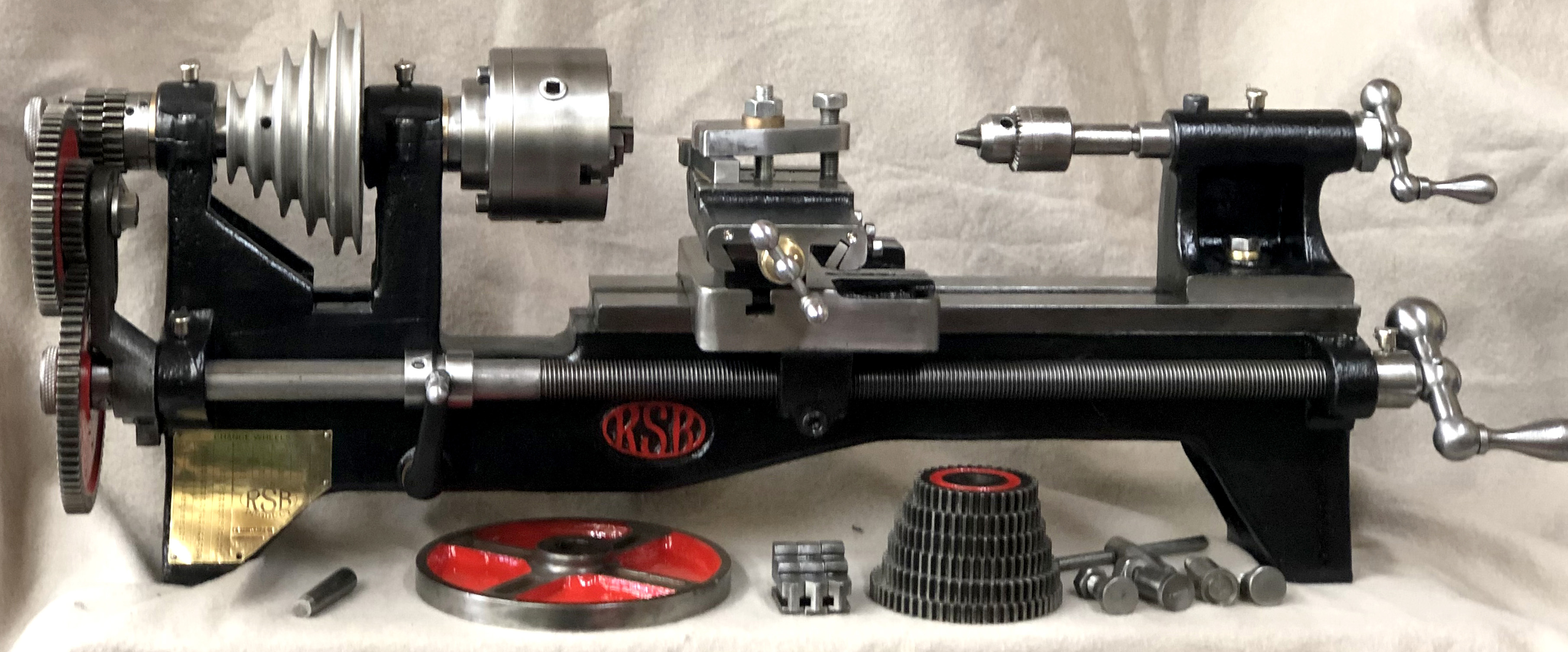 �..Live a Quiet Life & Work with your Hands
-
24th February 2014, 03:18 PM #4
GOLD MEMBER
- Join Date
- Dec 2007
- Location
- Melbourne
- Posts
- 3,277
Started cleaning it up today.
I'm wondering if this is mean't to be a ball race for a bearing?? Also what are you supposed to use to tighten those collars? It looks like they have used a mallet & punch.
IMG_4904.jpgIMG_4905.jpg
Not quite sure why this grub screw also has a nut.
IMG_4906.jpgIMG_4907.jpg
IMG_4908.jpg
Rear mount point for the pulleys to the base or motor mount.
IMG_4909.jpgIMG_4910.jpgIMG_4911.jpg
Table.
IMG_4912.jpg
Feed handle raises the quill and gravity feeds it, I think maybe a spring is missing from the top which would reverse this.
IMG_4913.jpg�..Live a Quiet Life & Work with your Hands
-
24th February 2014, 05:53 PM #5
SENIOR MEMBER
- Join Date
- Jun 2012
- Location
- SA
- Posts
- 1,478
Looks to be an adjuster for side play on the quill. Originally Posted by DSEL74
The lock nut holds the setting.
May be a brass or bronze plug at the end of the bolt ?
RobThe worst that can happen is you will fail.
But at least you tried.
-
24th February 2014, 09:05 PM #6
Senior Member
- Join Date
- Mar 2009
- Location
- Melbourne
- Age
- 54
- Posts
- 380
G'day Desel,
I reckon the v-belt pulley is not original and would have originally been a flat belt type.
The drill in the attached brochure page, although a bit different, might give you an idea as to how the idler pulleys might have originally been set up on yours.
If I had to guess I would bet that yours was driven from an overhead shaft so the idlers would be positioned for the belt coming from above rather than below like the one in the brochure.
It looks like a really nice restoration project, good luck and be sure to show us how she finishes up.
Cheers,
Greg.
-
24th February 2014, 09:30 PM #7
GOLD MEMBER
- Join Date
- Dec 2007
- Location
- Melbourne
- Posts
- 3,277
Yes that drill is "similar" and the vee pulley is definitely an add on as is the fabricated motor mount. It would have originally been flat belt drive, and set up in terms of pulleys very similar to the burke, which is the same as the junior and many others. Mine is actually a bigger drill than those but still a bench top drill.
Some did have a main drive pulley which connected to the line drive, others had their own motor at the base and connected where the line drive would be. These must have been around over a crossover period. Which of these mine was originally is unknown. Although based on the history of the RSB lathe it suggests that this was an late 1800s drill.
Actually re reading the image you found it says that, that model came in line drive and motor drive options.
I wonder what size the pulleys would have been and if there are some I can find or maybe some cast iron castors that could be adapted?�..Live a Quiet Life & Work with your Hands
-
25th February 2014, 10:11 AM #8
GOLD MEMBER
- Join Date
- Dec 2007
- Location
- Melbourne
- Posts
- 3,277
This is how I would eventually like to have this drill set up.

Only two speed or 3 speed maybe.
I estimate the large pulley should be about 4"x1⅜" and the speed of the driving pulley (aka motor speed?) 550 RPM based on various brochures.

This unit in the picture is a 10" Drill which has a height of 27�" Mine at a guess would be more like 40"
Any ideas on where I could get flat pulleys or what diameters I should be using???? were the belts a standard width 1�"???�..Live a Quiet Life & Work with your Hands
-
26th February 2014, 06:50 PM #9
GOLD MEMBER
- Join Date
- Dec 2007
- Location
- Melbourne
- Posts
- 3,277
Definitely think this was a thrust bearing but it has been castrated & lost its balls
Thrust Bearing No Balls - 31.jpgLast Import - 03.jpgLast Import - 04.jpgBearing Groove on Rack - 22.jpg
Keyway has seen better days.
Bearing locking rings keyway - 20.jpgKeyway - 19.jpg
Last Import - 24.jpgLast Import - 32.jpgLocking Rings - 21.jpgMatching Faces - 25.jpgMatching Faces - 26.jpg
Really thinking there is something missing from in here, There is a pin on each half and those flats must have served some purpose? Maybe a return spring?????? Any ideas??
Missing Spring Mechanisim maybe - 27.jpgMissing Spring Mechanisim maybe - 28.jpg
Cam and locking screw - 09.jpgCam in place - 08.jpgFeed Housing - 07.jpgFeed Housing complete- 06.jpg
Rack & pinion show a little bit of wear.
Pinion - 11.jpgPinion - 12.jpgRack- 23.jpg
Rear Mount Point - 29.jpgRear Mount Point - 30.jpg
This grub screw and nut hold the sleeve in place with that groove, do you think this is correct or modified??
Sleeve locking grubs screw & nut.jpgLast Import - 02.jpg
The butchered grub screw here which has definitely been a hack job is filled on the end to work as a key. What should it have been?????
Sleeve with grub screw key- 17.jpgSleeve with grub screw key.jpg Last Import - 01.jpg
Spindle assembled - 18.jpg�..Live a Quiet Life & Work with your Hands
-
26th February 2014, 10:25 PM #10
GOLD MEMBER
- Join Date
- Aug 2009
- Location
- Armadale Perth WA
- Age
- 55
- Posts
- 4,524
You might ask on the antique machinery section ... there are some post-drill guys there ... Vann for one ...
Re Alex Miller, I tried to find stuff here: https://www.woodworkforums.com/f152/dirtiest-own-181854
They were still in Melbourne 1972 at least ... from one of the photos.
They must have had outlets all over the place.
Cheers,
Paul
-
26th February 2014, 10:45 PM #11
Blacksmith, Cabinetmaker, Machinist, Messmaker
- Join Date
- Dec 2011
- Location
- Canberra
- Age
- 40
- Posts
- 4,467
Thanks for all the pics, she looks like a beauty.
Sure looks like there should be a return spring in there to me.
Cheers,
Ew1915 17"x50" LeBlond heavy duty Lathe, 24" Queen city shaper, 1970's G Vernier FV.3.TO Universal Mill, 1958 Blohm HFS 6 surface grinder, 1942 Rivett 715 Lathe, 14"x40" Antrac Lathe, Startrite H225 Bandsaw, 1949 Hercus Camelback Drill press, 1947 Holbrook C10 Lathe.
-
26th February 2014, 11:29 PM #12
GOLD MEMBER
- Join Date
- Dec 2007
- Location
- Melbourne
- Posts
- 3,277
Paul, thanks for the link. Looks like you found quite a few outlets.
Ew, I wonder if just a simple expansion spring was all it was or the two angled flats indicate more??
I have so many questions and the is so little info I can find. Some photos or adverts for "similar" drills, but they still don't show what is inside!
I'd love to know what mounted at the base? I can only assume it was a bracket for the stepped pulleys.
I deduce there was a two position arm with a locking screw at the elbow with guide pulleys. As the belt turns 90 deg over those guides I am thinking the tangent of the pulley would align with the centre of the drive pulley?? If I figure out the pulleys I can then work out the arc of the arm as it rotates between positions hopefully. Would the guide pulleys have bearings, or just greased up steel on steel? There isn't any bearings any where except for the one (thrust bearing) I believe should have been in the spindle.
How much crowning is required on the pulley and how much wider than the belt would they be?
What size would the second stepped pulley be if the larger was 4�" and how do I calculate the ratio of the pulley at the top to the pulley at the bottom and then to the drive pulley and to the rpm of the motor to get the correct drill speed. That is too much maths for me!
I also would like to know how the remove the chuck from the spindle. My guess is the spindle has a short taper which friction fits into the chuck?
This one might be easier to answer, drill chuck keys do they come in standard sizes?? It is missing on this drill and doesn't match the three keys I have. The chuck is un branded.
How hard would it be to set the table up perpendicular to the column and have the raised portion of the table redone on a surface grinder???
Ok I'll stop babbling on now����..�..Live a Quiet Life & Work with your Hands
-
27th February 2014, 06:23 AM #13
SENIOR MEMBER
- Join Date
- Sep 2011
- Location
- Ballarat
- Age
- 65
- Posts
- 2,659
Hi Dale, Originally Posted by DSEL74
I have info on the crowning of pulleys that I will dig up for you.
I also found the sheet you drew up for the drill specs you were after a while back (must do that).
Another thing I will try and locate at work is a 'Miller' brochure or any info we may have on them as a fair bit of our mining machinery came from Millers.
Great bit of work so far by the way.
Phil
-
27th February 2014, 11:24 AM #14
GOLD MEMBER
- Join Date
- Dec 2007
- Location
- Melbourne
- Posts
- 3,277
Originally Posted by Steamwhisperer
Thanks Phil it be much appreciated.
I have been going over my options for the pulleys, finding existing ones (unlikely), modifying some steel castors (limited in size & width), making some seems like what I will have to do. I have considered steel, brass, and wooden ones. I may go with wooden ones at least to start with as a prototype, as you know many prototypes end up working so well they never get upgraded. I know the large wooden ones were segmented, in your experience do you think solid ones would work fine, and should the shaft run parallel to the grain?
I'm thinking the chuck may be removed like this??
 �..Live a Quiet Life & Work with your Hands
-
28th February 2014, 09:23 AM #15
SENIOR MEMBER
- Join Date
- Sep 2011
- Location
- Ballarat
- Age
- 65
- Posts
- 2,659
Here is a start. I know I have more so I will keep searching.
Phil


Similar Threads
-
Just heard
By fenderbelly in forum WOODIES JOKESReplies: 2Last Post: 1st March 2012, 09:41 PM -
You Have Heard the Saying
By Barry_White in forum WOODIES JOKESReplies: 1Last Post: 9th February 2007, 09:31 PM -
You heard it here first
By Flowboy in forum FESTOOL FORUMReplies: 2Last Post: 21st July 2006, 06:09 AM
