

 Thanks:
  Likes:
  Needs Pictures:
  Picture(s) thanks:
Results 1 to 15 of 56
Thread: HM50 Can 'O' worms.....
-
26th June 2012, 08:29 PM #1
 Blacksmith, Cabinetmaker, Machinist, Messmaker


- Join Date
- Dec 2011
- Location
- Canberra
- Age
- 40
- Posts
- 4,467
 HM50 Can 'O' worms, scrape or not?
Hi,
Firstly, its all Stuarts fault...... (joke) Without his saddle thread i probably wouldn't have even looked.
A coolant change and cleanout has lead to a clean......and dismantle.....and OMG what have i done????? Other than to clean all the Chinese muck out, the reason i dismantled the mill was to adjust the height of the X screw nut, split the X and Y nuts and make sure the lube grooves where up to scratch.
Unlike Simon's i my machine needed very little work to get the lube channels O.k Just minor things like opening up the channels so the feed hole actually fed them......
Like Simons there is no provision to get oil into the dovetails in either axis. The knee is not off (yet) but i expect it to be the same. Thats the easy bit....
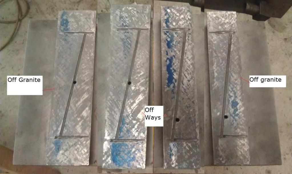
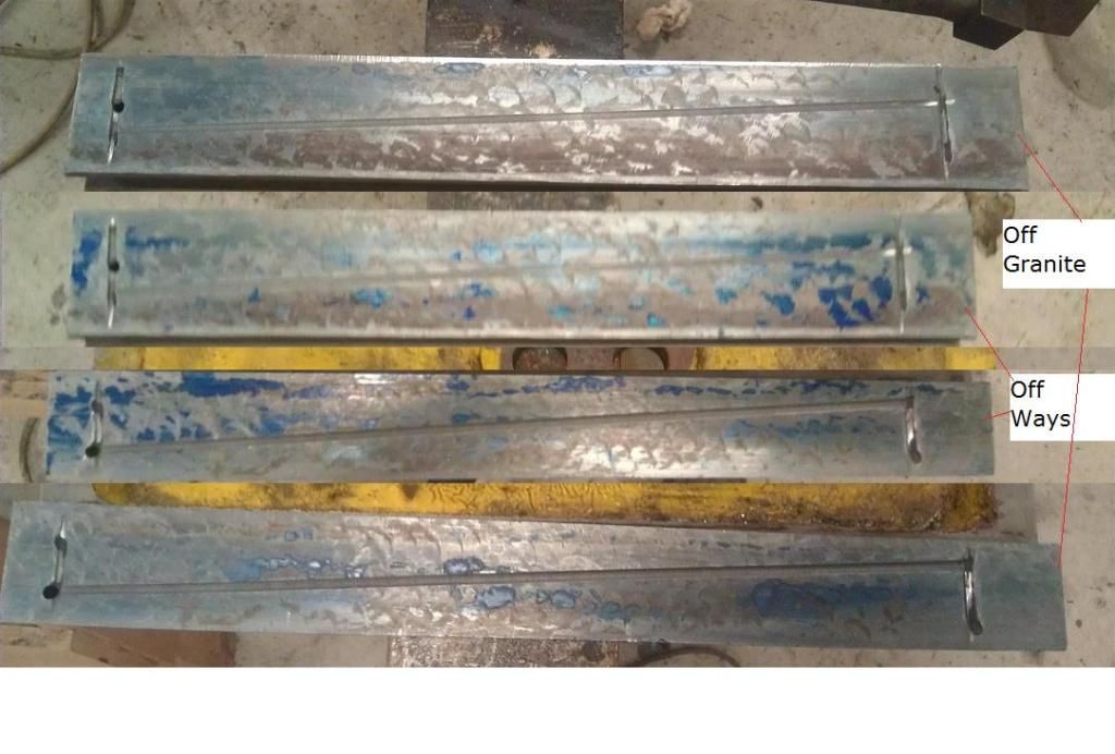
While there i decided to blue the table and knee ways and spot the female (short) haves of the dovetails. The Y way scraping looks pretty good, no flaking though and a few VERY rough patches. The X is flaked but has some wear and all the scrapping looks to be done with an axe.....or maybe a big hammer......
The ground/milled surfaces of the table and knee show almost no signs of wear, so i am thinking that spotting off them should be o.k.
The table and Knee ways:
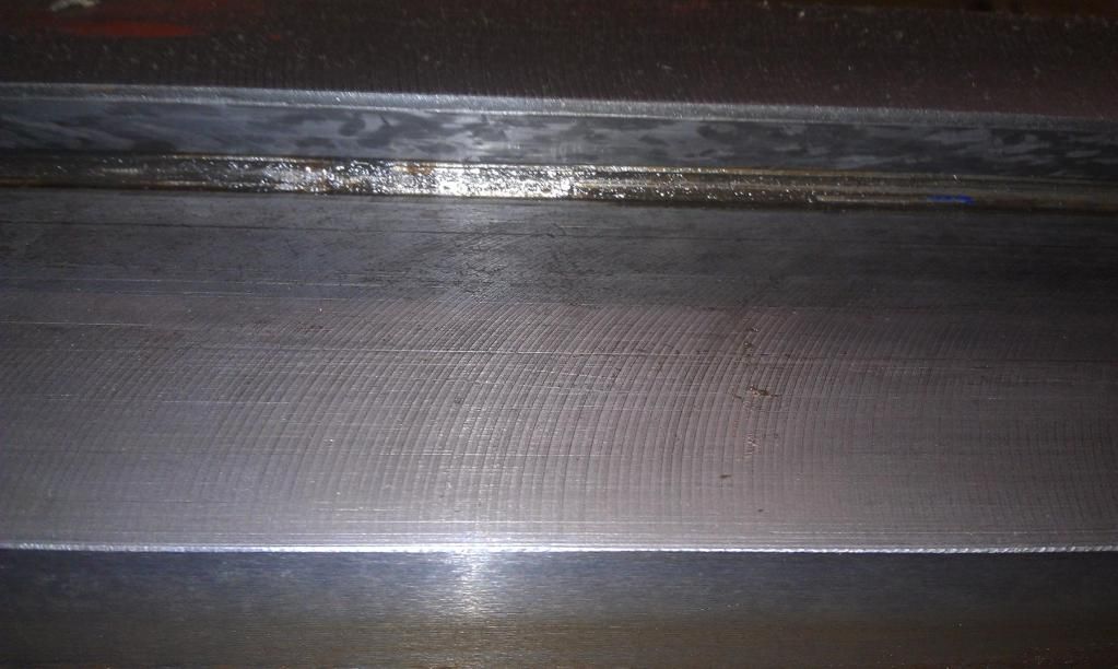
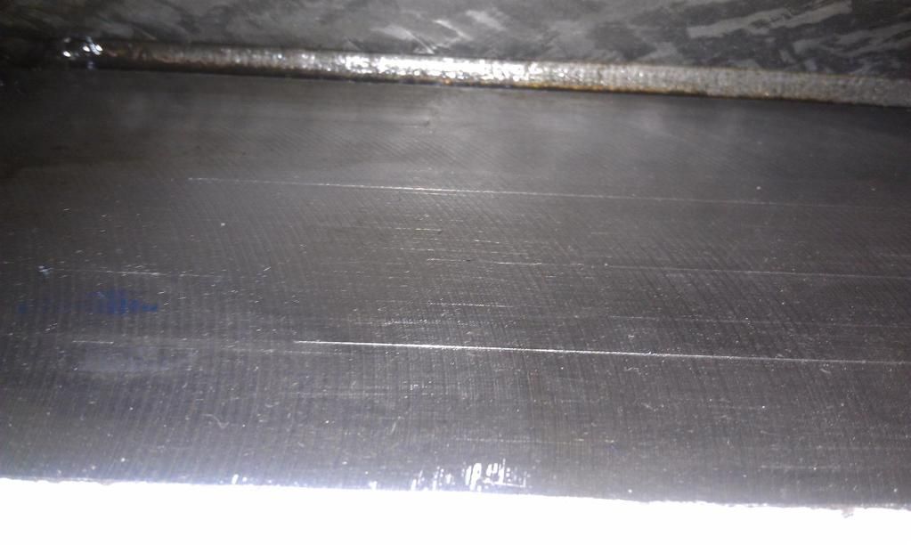
The spotting on the 2 ways....not good.....but it could be a lot worse
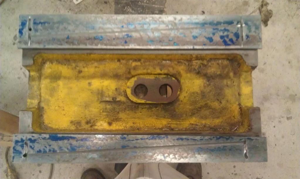
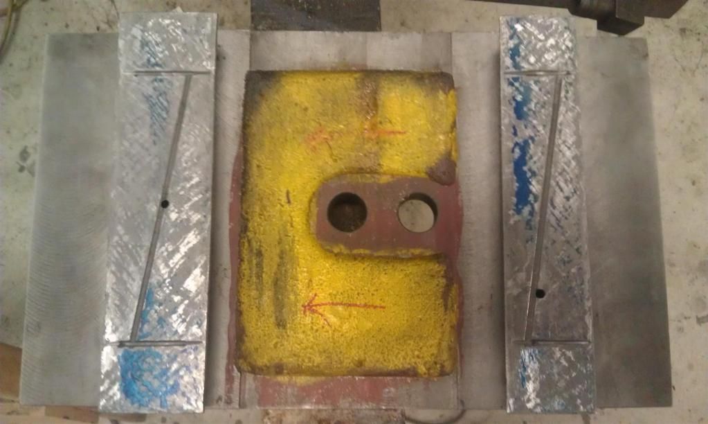
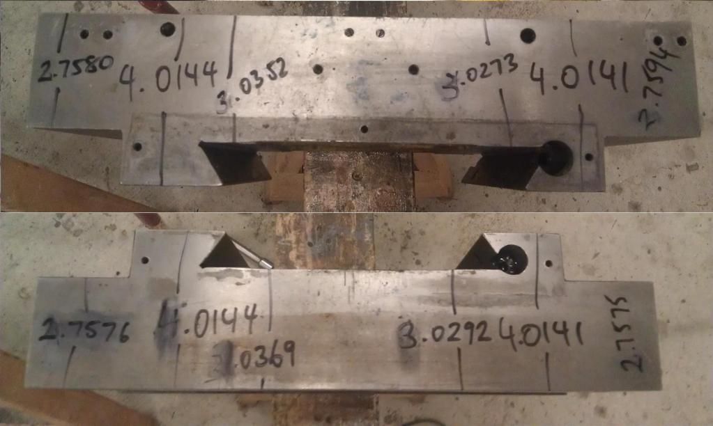
Finally i spent some time with a mic and measured the.....don't know what to call it....saddle? The number in the 4" range is from each way, i aimed to mic off the high spots. The other 2 numbers on each side are of the other machined surfaces to see if i could get an idea of which axis the error is on, but none of the surfaces seems to be in the same plane as the ways. The other thing is the .0003" error in the "saddle" could be there to compensate for a badly machined knee..... All i can think of is RC.'s plan, plan plan.......to be honest i almost just want to put it all back together and ignore it but i don't think i can.....
 1915 17"x50" LeBlond heavy duty Lathe, 24" Queen city shaper, 1970's G Vernier FV.3.TO Universal Mill, 1958 Blohm HFS 6 surface grinder, 1942 Rivett 715 Lathe, 14"x40" Antrac Lathe, Startrite H225 Bandsaw, 1949 Hercus Camelback Drill press, 1947 Holbrook C10 Lathe.
-
26th June 2012 08:29 PM # ADSGoogle Adsense Advertisement
- Join Date
- Always
- Location
- Advertising world
- Age
- 2010
- Posts
- Many
-
26th June 2012, 09:00 PM #2
GOLD MEMBER
- Join Date
- Jul 2010
- Location
- Melbourne
- Posts
- 7,775
Hi Ewan,
And here I was thinking my thread would serve as a warning
"see if i could get an idea of which axis the error is on" What error? Is there something you are looking to fix?
I assume you dont have a surface plate?
You cant be sure the ground/milled surfaces of the table and knee are any flatter than the saddle. Trying to use them as a master could give you problems(says a guy that is doing just that, but I have tried to be sure they are "pretty" flat and will likely one day revisit them anyway, infact I am only scraping the saddle:bed ways to be sure I get consistant readings when squaring the cross-silde)
Stuart
-
26th June 2012, 09:09 PM #3
Blacksmith, Cabinetmaker, Machinist, Messmaker
- Join Date
- Dec 2011
- Location
- Canberra
- Age
- 40
- Posts
- 4,467
Hi Stuart Originally Posted by Stustoys

The Saddle is .0003" thicker on the LHS. whenever i have trammed the machine head for vertical with the quill, it is out when you use the Z axis (does that make sense?) In other words the table is not perpendicular to the Z ways.
I only have a carbatec granite plate, 300x250, so making a master to check the ground ways is a bit hard, so is measuring the saddle for parallel with a DTI. The .0003" error is off repeated measuring with a mic.1915 17"x50" LeBlond heavy duty Lathe, 24" Queen city shaper, 1970's G Vernier FV.3.TO Universal Mill, 1958 Blohm HFS 6 surface grinder, 1942 Rivett 715 Lathe, 14"x40" Antrac Lathe, Startrite H225 Bandsaw, 1949 Hercus Camelback Drill press, 1947 Holbrook C10 Lathe.
-
26th June 2012, 09:40 PM #4Dave J Guest
Hi Ewan,
You will be amazed at the crap left in these mills. My first mill had the Y axis ways just milled like yours, and this was one of my complaints to H&F because they are advertised as precision ground slides?
It looks like that accordion cover has held swarf under it like you said and that has caused those scratches in the ways.
It still amazes me at the variety of castings these mills have. With your 4th picture, the first and second mill I had the surface was just flat, where the mill I have now they save the cast iron by hollowing it out like yours (my picture below). It doesn't have much affect on the strength, but it just goes to show the corners they cut to save money and this cant be seen until you pull it apart.
The same with your third picture where mine has ribs where your's doesn't.
So anyone reading this thread and thinking of buying one, there are many inconsistencies with these mills and you will never now what your going to get until you pull it down and look.
With splitting the nuts for backlash I cut through mine all but about 5-7mm as seen in the pictures below and then used 2x M4 grub screws in each corner. For adjusting them because the X is so far it, I just drilled the end of a piece of 10mm round bar and tack welded a cut off allen key in it for adjusting it. On the other end I welded a small piece across to make a T handle to turn it.
Dave
-
26th June 2012, 11:35 PM #5
Blacksmith, Cabinetmaker, Machinist, Messmaker
- Join Date
- Dec 2011
- Location
- Canberra
- Age
- 40
- Posts
- 4,467
Hi Dave,
Looking at your pics it just occurred to me that you have a 52 so you have a swivel table. My knee has both X and Y dovetails on the one piece of cast. Is that scraping original? It looks like a much better job than mine, almost like the person knew what they were doing.....having said that i think 2 different people scraped mine, one for the x and one for the y, the y is much "neater" than the x but still not mating very well.
Also, are your bronze nuts bolted on? my y one has a screw and washer from the top side of the casting but the x one was only pressed in place.
I got some 1.5mm rubber from clarks yesterday so the accordion cover is in the bin, where it belongs......
1915 17"x50" LeBlond heavy duty Lathe, 24" Queen city shaper, 1970's G Vernier FV.3.TO Universal Mill, 1958 Blohm HFS 6 surface grinder, 1942 Rivett 715 Lathe, 14"x40" Antrac Lathe, Startrite H225 Bandsaw, 1949 Hercus Camelback Drill press, 1947 Holbrook C10 Lathe.
-
27th June 2012, 12:14 AM #6
GOLD MEMBER
- Join Date
- Jul 2010
- Location
- Melbourne
- Posts
- 7,775
No not really Originally Posted by Ueee
 Yeah I see the 0.0003" error, but thats over want? 12". How did you pick that up with the Z?
Can you fit the saddle on the plate? (I guess not?)
Hi Dave,
You have the swivel table.
Stuart
-
27th June 2012, 12:49 AM #7Dave J Guest
I haven't touched the scraping, but I have never had it on a surface plate either, LOL
My X nut is just pressed in as well and the Y is bolted in like yours. I was not happy with it but it is a press fit, and rather than mod it for the original nut I thought I would leave it until I fit the ball screw and double nuts and fix them properly.
In the picture below you can see the shim I needed to add to bring the Y nut down into alignment.
I would recommend taking the knee off just to check, in the pictures below you can see what I found in the oilers and holes.
The rubber will make a huge difference, I never have to clean under mine for swarf and only lift it up to oil it. 2 drilled and tapped holes in the collar on top of the column will allow you to mount a bit of 25x5mm flat bar to hang the rubber from and I used a bit of 10x3mm on top of the rubber and then sandwiched the rubber between them with pop rivets. I think from memory mine is around 75-100mm out either side and this also covers the DRO scale from anything.
It also makes the coolant flow strait down into the tray instead on on the knee. For the brackets to go onto the way wipers I used a bit of angle sheet metal around 1.2mm thick as I had a stack laying around.
Dave
-
27th June 2012, 08:11 AM #8
GOLD MEMBER

- Join Date
- Aug 2011
- Location
- Melbourne
- Posts
- 2,951
Hi guys,
Can someone please explain or show me how you fit a wiper to the saddle when the gibb strip and the head of the adjustment bolt sit proud of the saddle by a good 1/2"? Do I have to wait for another 10 years of wear until the gibb slides in further?")
Hi Ewan,
how did you measure the differences in the saddles height and spot the saddle? I have one of the carbatec surface plates too and it's too small to sit the saddle on let alone the DI and base!
Cheers,
Simon
-
27th June 2012, 02:38 PM #9Dave J Guest
With you getting into scraping and being early days for the mill, I would just make the way wiper around it. Who knows in the future you might end up scraping it in and need that extra bit.
Saying that you could just scrap the gib for a better fit with whats there. Nick has a video showing the bluing of the gib and taping it in and then scraping it, this could be done with nothing else being done and would seat the gib in better.
Dave
-
27th June 2012, 02:41 PM #10Dave J Guest
Just another thought, while it's apart put the gib into position and see what the maximum adjustment is. Anything over hanging after that is useless anyway and can be cut off.
Dave
-
27th June 2012, 03:09 PM #11
GOLD MEMBER
- Join Date
- Aug 2011
- Location
- Melbourne
- Posts
- 2,951
Hi Dave,
thanks for the reply. I figured they were my options. I think I will cut around it at this stage as you don't have to take much off the gibb strip for it to require it's full insertion and I think I would be mad to cut off anything at this stage. I have made the front wiper plate today and have opted to work around not only the gibb strip but also the adjustment bolt as its' proud as well. It certainly won't be in the future!
Anyway, this is Ueee's thread so enough from me!
Cheers,
Simon
-
27th June 2012, 11:32 PM #12
Blacksmith, Cabinetmaker, Machinist, Messmaker
- Join Date
- Dec 2011
- Location
- Canberra
- Age
- 40
- Posts
- 4,467
Hi Simon, Originally Posted by simonl
The measurements were micrometer readings from each way. I also used a DI on each corner of the saddle x ways off the Knee Y ways.
I don't know if you have your Y screw off but if you do i hope you don't have my problems getting it back on "right". (see below)
I will also have the same problem with the back of the Y gib and a wiper, but being the back i can just cut the gib down a bit......1915 17"x50" LeBlond heavy duty Lathe, 24" Queen city shaper, 1970's G Vernier FV.3.TO Universal Mill, 1958 Blohm HFS 6 surface grinder, 1942 Rivett 715 Lathe, 14"x40" Antrac Lathe, Startrite H225 Bandsaw, 1949 Hercus Camelback Drill press, 1947 Holbrook C10 Lathe.
-
27th June 2012, 11:42 PM #13
GOLD MEMBER
- Join Date
- Aug 2011
- Location
- Melbourne
- Posts
- 2,951
Hi Ewan,
I see. Not sure what problems you mean in relation to the Y screw? were you supposed to attach a pic?
I had a few other problems that I sorted shortly after I got the mill. Mostly the preload on the X thrust bearing was non existent allowing a few mm backlash. Also the Y nut in the leadscrew was mis-aligned and was binding when brought fully forward and closest to the thrust bearing. It turned out that the nut was not only sitting too high but the bearing mount housing the thrust bearing was also not parallel. I had to machine the Y leadscrew nut and then take a bit off the thrust bearing housing. Both leadscrew nuts are pretty crap. I'd love to replace them but I can't see myself cutting an internal ACME thread anytime soon!
Cheers,
Simon
-
28th June 2012, 12:26 AM #14
Blacksmith, Cabinetmaker, Machinist, Messmaker
- Join Date
- Dec 2011
- Location
- Canberra
- Age
- 40
- Posts
- 4,467
Hi,
After Stu's comment about a surface plate the first thing i did today was run my small plate over the ways to see how it compared to the spotting of the ways.
Lets just say my can is now a bucket.....The milled ways are clearly not very good, not in the same plane as each other and clearly i was very lucky to repeatedly get mic readings to 1/10 000".......There is no way i will be touching anything, the milled ways clearly need a lot of work.
With a straight edge across the saddle y ways the non gib side looks pretty good, certainly no space for a 1thou feeler. The gib side however leans up enough to get a 1.5 thou feeler in. After finding this i just didn't bother checking the X way, the spotting says it all.
I then put the saddle back on.....easy right? firstly i cleaned and re-assembled the thrust bearings in the y screw. They were pretty sloppy so a little machining and some shim made them firm and the handle spun nicely. Here was me thinking, "hey i've just get rid of some of my backlash".....yeah right!
Then i put the screw in and tightened up the retaining screws. The handle is as tight as a fishes a#####e.......Turns out either the journal or seat (or probably both) are not machined perpendicular to the screws axis and the slop in the bearings allowed the journal to sit skewed.....To top it off the natural sitting point of the journal is way off the pin location.....
I should not be surprised, but i'm pretty of at the whole thing right now.....just the fact that to fix bad machining they have left slop in bearings goes right against everything i have ever been taught! So Simon......i hope yours is not like this!
To top it off i pinched a nerve between my shoulder blades and i just now i'm not going to sleep well tonight 1915 17"x50" LeBlond heavy duty Lathe, 24" Queen city shaper, 1970's G Vernier FV.3.TO Universal Mill, 1958 Blohm HFS 6 surface grinder, 1942 Rivett 715 Lathe, 14"x40" Antrac Lathe, Startrite H225 Bandsaw, 1949 Hercus Camelback Drill press, 1947 Holbrook C10 Lathe.
-
28th June 2012, 12:28 AM #15
Blacksmith, Cabinetmaker, Machinist, Messmaker
- Join Date
- Dec 2011
- Location
- Canberra
- Age
- 40
- Posts
- 4,467
Sorry Simon, Originally Posted by simonl
Got caught on Daddy duty.....wasn't supposed to be such a delay between posts. Sounds like yours is already sorted anyway.....1915 17"x50" LeBlond heavy duty Lathe, 24" Queen city shaper, 1970's G Vernier FV.3.TO Universal Mill, 1958 Blohm HFS 6 surface grinder, 1942 Rivett 715 Lathe, 14"x40" Antrac Lathe, Startrite H225 Bandsaw, 1949 Hercus Camelback Drill press, 1947 Holbrook C10 Lathe.


Similar Threads
-
HM50/52 Y way covers
By Ueee in forum METALWORK FORUMReplies: 6Last Post: 22nd June 2012, 09:36 PM -
Worms
By Calm in forum WOODIES JOKESReplies: 3Last Post: 19th June 2010, 07:23 PM -
worms in cedar
By ralphtaff in forum WOODTURNING - GENERALReplies: 14Last Post: 25th February 2009, 05:20 PM -
Can of Worms
By Felder in forum WOODIES JOKESReplies: 0Last Post: 13th April 2007, 10:54 AM
