

 Thanks:
  Likes:
  Needs Pictures:
  Picture(s) thanks:
Results 136 to 150 of 183
Thread: HM52 CNC Conversion
-
27th May 2010, 06:53 PM #136
 GOLD MEMBER


- Join Date
- Jun 2007
- Location
- sydney
- Age
- 64
- Posts
- 3,566

Dont get confused though that opperation was done with the Vertical Head with the job Horizontal.
-
27th May 2010 06:53 PM # ADSGoogle Adsense Advertisement
- Join Date
- Always
- Location
- Advertising world
- Age
- 2010
- Posts
- Many
-
27th May 2010, 06:59 PM #137
GOLD MEMBER
- Join Date
- Jul 2006
- Location
- Adelaide
- Posts
- 2,680
 Originally Posted by pipeclay

Hells bells....just when i thought i had it you toss another spanner in the works..hahaha
-
27th May 2010, 07:19 PM #138
GOLD MEMBER
- Join Date
- Jun 2008
- Location
- Victoria, Australia
- Age
- 74
- Posts
- 6,132
Hi Eskimo,
Maybe I can confuse you further....
There are many ways to cut teeth, they all amount to the same thing you need an accurate way of rotating the part with some kind of indexing system, and a way of controlling the cut for each pass. I remember seeing one somewhere where the guy just used a paper disk with lines on it to index the position for each cut.
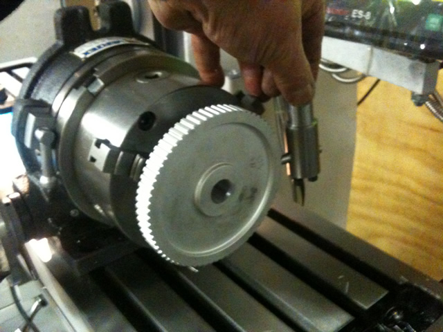
The way we had it set up was with the fly cutter in the vertical spindle The gear mounted vertically using a three jaw chuck on the rotary table and used the X axis for each pass, and the Y axis to control the depth of cut. The knee and quill are locked so that the cutter is on the center line of the gear. Bring the cutter across using the Y axis to set the depth of cut and then run the Xaxis across to cut each tooth using however many passes. Then index the rotary table to the next tooth position and repeat the process. I have to make another in the next few days, so I'll remember to take a picture. The one we fixed works fine, but the reduction in diameter means it will be too small for some of the change gears, might as well make on the right size from Aluminium, I'm not a big fan of plastic gears for lathes, I'd much rather they put a shear pin somewhere... (another project) rather than stripping teeth.
The way Pipeclay suggested using the horizontal spindle to hold the cutter and using knee for depth of cut is probably better. Amounts to much the same I think.
Another way is to use a lathe and the fly cutter goes in the spindle, and the depth of cut is controlled by the cross slide.
Regards
Ray
-
27th May 2010, 08:25 PM #139
GOLD MEMBER
- Join Date
- Jul 2006
- Location
- Adelaide
- Posts
- 2,680
mum gave me a teething ring..... Originally Posted by RayG
i'll peruse what you said and ponder what it all means later this evening
-
27th May 2010, 08:45 PM #140
GOLD MEMBER
- Join Date
- Jun 2007
- Location
- sydney
- Age
- 64
- Posts
- 3,566
Ray from your First description it sounded as though you had the Rotary Table in the Vertical Position,my explanation to Eskimo was based on that.
From what you have said now it appears that your Rotary Table was mounted Horizontally.
-
27th May 2010, 09:37 PM #141
GOLD MEMBER
- Join Date
- Jun 2008
- Location
- Victoria, Australia
- Age
- 74
- Posts
- 6,132
Hi Pipeclay,
Yes, axis of the rotary table is horizontal, holding the part vertical. I should have said the rotary table was horizontal.
(I did however say that the gear was vertical)
Like this.
Regards
Ray
-
27th May 2010, 09:42 PM #142
GOLD MEMBER
- Join Date
- Jun 2007
- Location
- sydney
- Age
- 64
- Posts
- 3,566
The picture would of helped,At least now I wont confuse Eskimo any more.
-
28th May 2010, 08:34 AM #143
GOLD MEMBER
- Join Date
- Jul 2006
- Location
- Adelaide
- Posts
- 2,680
thanks Ray and Pipeclay for being patient, much appreciated Originally Posted by pipeclay
the bit that the rotary table was vertical was that which was throwing me...but although I have now been made fully aware of how Ray did it I am still having trouble picturing to see how its done using Pipeclay's definition if the table was also being indexed?...lets leave it at that forthe time being......some one will do it one day and take photos ...i hope
Next time guys do everything in triplicate or more with 3 lots of photos for "Dummies Like Me at Milling"
Thanks again

-
1st June 2010, 07:36 PM #144
GOLD MEMBER
- Join Date
- Jun 2008
- Location
- Victoria, Australia
- Age
- 74
- Posts
- 6,132
Still working on the X axis ball-screw conversion...
Milling out the ballnut mounting.
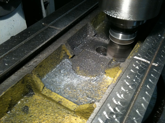
Since the X axis is removed the head is rotated and cut is performed using Y axis only. Unfortunately we screwed up somewhere with the dimensions and we will need to go a little deeper and put in a spacer to get full support across the width of the ballnut support block... The other screw-up was that the ballscrew axis is offset slightly on the saddle. So we had to take a bit off the side of the ballnut mounting block.
After getting it all together, the table was assembled with the ballscrew and the ballnut mounting screws were fitted loosely and we ran the table back and forward tightening the bolts down a little at a time to make sure the alignment was good and we didn't get any binding.
I was expecting the backlash to be zero, but we are getting about 0.04mm (1.6 thou) not too bad, when we lock everything down finally I'm hoping for better, but I'm not unhappy as it is anyway.
Josh is going to continue the conversion for the next few weeks, I'm off overseas to help my eldest son with an artwork project in Austria for 5 weeks. Josh will keep the project moving nicely and regular updates will contine.
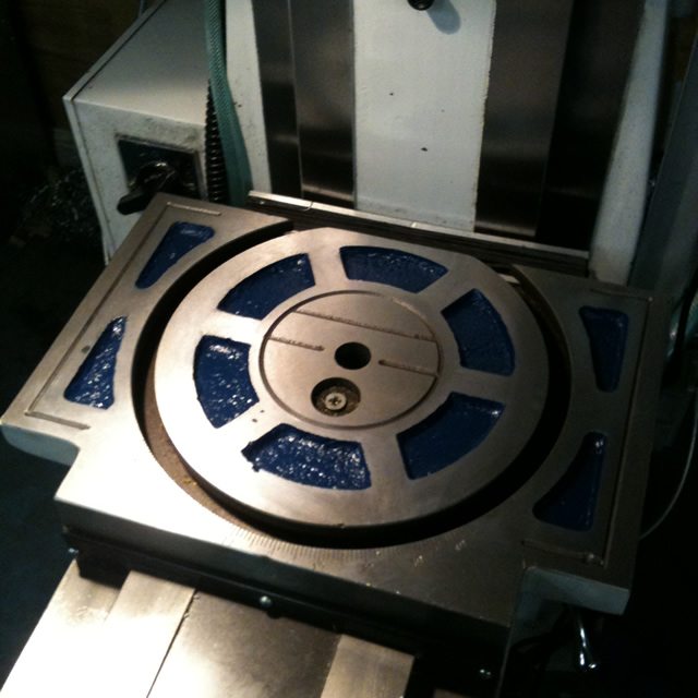
Since Dave has a monopoly on red and black, we have to go for a different color scheme..
Next step is to re-do the machining on the ballnut support and then we are pretty close to putting the table back on the machine...
Regards
Ray
-
10th July 2010, 02:11 PM #145Dave J Guest
Hi Ray,
I thought I would post the link here as well to keep it all together for people who are following this thread, instead of it being all over the place.
While looking through CNC zone last night I came across the link below and thought it might be of interest to you. It's a nut driven quill drive for a mill/drill. You might get some ideas from it. The unit is shown in post number 93
Mill/Drill conversion coming right up! - Page 3 - CNCzone.com-The Largest Machinist Community on the net!
Has your son done much on the mill since you have been away?
Dave
-
11th July 2010, 10:49 AM #146
GOLD MEMBER
- Join Date
- Jun 2008
- Location
- Victoria, Australia
- Age
- 74
- Posts
- 6,132
Hi Dave,
We currently have the mill back together, with just the X-axis running on ball screws. The backlash is about 1 thou, which Josh thinks is actually the 1/2" aluminium plate which mounts the AC bearings flexing minutely, (he is probably right.) The table runs smoothly and easily from end to end and gives a very nice "feel" to the manual operation. One unexpected result of the conversion is that the power feed runs right down to very slow speeds.
Josh has been busy making parts for the art-work project, so not much activity on the CNC conversion.
Anyway, the next job is to take what we have learnt from the X-axis conversion and apply it to the Y-axis.
Thanks for the link to that Z-axis drive setup, not sure I understand exactly how he has done it, from the pictures it looks like a bearing mounted on the outside of the ball nut? Is there an AC bearing under the ballnut?
Regards
Ray
-
29th July 2010, 10:47 PM #147Dave J Guest
Hi Ray,
Here is a picture I drew up to help you out with some ideas for the quill.
Dave
-
29th July 2010, 11:48 PM #148
GOLD MEMBER
- Join Date
- Jun 2008
- Location
- Victoria, Australia
- Age
- 74
- Posts
- 6,132
Hi Dave,
I'm thinking along similar lines, with a few refinements to your drawing. The ball nut would need be mounted as low as possible to get maximum travel ( I think you picked up on this earlier on in this thread )
I need to think about what bearing setup would be needed, I'm thinking a pair of AC bearings mounted top and bottom of the ballnut and the drive gear fixed to the ballnut on the inside of the bearings. I don't think the sleeved arrangement in your drawing would work, but maybe I'm misreading the drawing.
Regards
Ray
-
30th July 2010, 12:15 AM #149Dave J Guest
Hi Ray,
You are right about the height, I only drew that picture tonight, I have put the brain into gear now (new picture below)
What I was thinking with the sleeve, was to press the steel sleeve onto the ball nut so there was something to machine to mount the AC bearings to. I don't think you would want to machine the ball nut outer to suit the bearings.
In the picture the pulley is attached to the top of the ball nut using 4 of the 6 mounting holes in it. I think bearings of this size would handle the cantilever of having the pulley on top no worries at all. To keep it central the pulley could be machined to suit the outer of the ball nut flange.
Dave
-
30th July 2010, 01:38 AM #150
GOLD MEMBER
- Join Date
- Jun 2008
- Location
- Victoria, Australia
- Age
- 74
- Posts
- 6,132
Hi Dave,
That looks closer, I've had a couple of goes at sketching up the bearing setup, but still haven't come up with an arrangement that I like.
The idea of pressing a sleeve onto the ballnut solves a few problems. Nice, you should have the flu more often..
One thing that keeps coming back as something that might be a good feature in the conversion is the ability to disengage the z-axis quill drive and use the manual quill feed, for simple drilling jobs etc.
With this arrangement you could just drop the nut off the bottom of the ball screw I think that might work, or maybe something as simple as a tapered locking pin would do the trick, also perhaps as a safety feature a extra locking collar on the ballscrew just underneath the ballnut so that if the z axis drive were to run when it was unlocked it wouldn't screw the ballnut off the end.. I can just imagine hitting the z drive on the pendant and the ballscrew unwinding off the nut scattering ball bearings all over the place..
I am set up to cast aluminium, brass and bronze ( can't do cast iron however) so I'm thinking of casting the mounting blocks.
Regards
Ray


Similar Threads
-
Hafco Hm52 on the fritz again
By Retromilling in forum METALWORK FORUMReplies: 25Last Post: 12th August 2009, 11:14 AM -
CNC conversion
By sonic_racing in forum METALWORK FORUMReplies: 7Last Post: 18th January 2009, 03:11 PM -
PSI conversion
By dmassey31 in forum WOODTURNING - PEN TURNINGReplies: 2Last Post: 26th November 2006, 09:03 AM -
Conversion of 3ph to 1ph
By MikeK in forum WOODWORK - GENERALReplies: 4Last Post: 2nd November 2005, 03:51 PM
