

 Thanks:
  Likes:
  Needs Pictures:
  Picture(s) thanks:
Results 91 to 105 of 183
Thread: HM52 CNC Conversion
-
13th May 2010, 08:36 AM #91
 GOLD MEMBER


- Join Date
- Jun 2007
- Location
- sydney
- Age
- 64
- Posts
- 3,566

Do you have a Plug or some other means of a Block to stopSwarf and Grit entering your Horizontal Spindle.
From the photo of you machining the Face in the vise it looks as if it is open.
-
13th May 2010 08:36 AM # ADSGoogle Adsense Advertisement
- Join Date
- Always
- Location
- Advertising world
- Age
- 2010
- Posts
- Many
-
13th May 2010, 05:04 PM #92
GOLD MEMBER
- Join Date
- Jun 2008
- Location
- Victoria, Australia
- Age
- 74
- Posts
- 6,132
Hi Dave,
Yes, the ballnut mounting surface has to be machined so that the ballscrew centerline lines up with the centerline of the endplate. It's going to be a bit tricky machining without the X-axis..
Hi Pipeclay,
No I don't have anything to plug the horizontal arbor, I should make something.
Regards
Ray
-
14th May 2010, 03:58 AM #93
GOLD MEMBER
- Join Date
- Jun 2008
- Location
- Victoria, Australia
- Age
- 74
- Posts
- 6,132
Time for a late night update
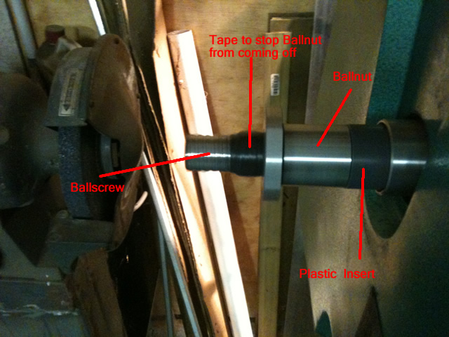
It's getting close to the time for machining the ballscrew ends, so I figure I should make sure it's going to work.
The critical things are, not to damage the ballscrews, so the ballscrew is held in a brass "collet" of sorts,
the ballscrew passes through the spindle and there is a plastic insert to center the ballscrew and provide a bit of support.
There is a few layers of tape to stop the ballnut from unwinding off the ballscrew.
I don't want to have to learn how to reload ballnuts just yet..
Here is the back of the lathe spindle.
The brass collet setup.
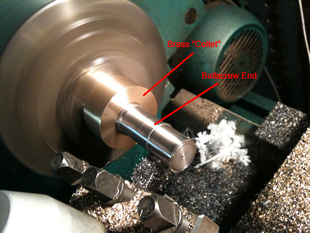
The brass "collet" is machined to be a sliding fit over the ballscrew, and I have cut slits in the section
where it is clamped by the chuck. The runout is checked with a dial test gauge. I didn't feel the need
for a center on the tailstock, but machining longer sections I might need it.
The ballscrew is hardened, but as RodM had pointed out earlier, one you get through the hardened threads
it went fairly smoothly with TC insert cutters. Light cuts and low feed rate until you get past the ball threads.
Interrupted cuts on hardened material (not to mention expensive parts) make for nervous machining...
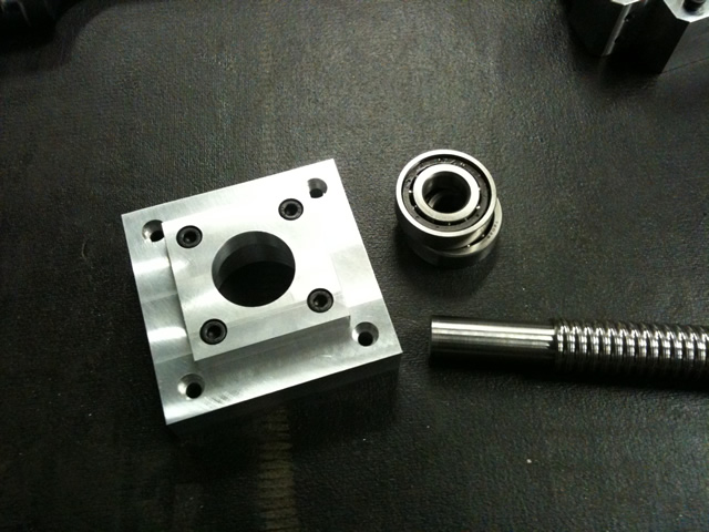
Here is the finished test part. With the AC bearings and bearing housing.
The idea here was just to do a test to see how easy it would be to setup and how hard it would be to machine,
expensive little things these ballscrews, can't afford to have any stuffups.
So far so good...
Regards
Ray
-
14th May 2010, 09:26 PM #94
GOLD MEMBER
- Join Date
- Jun 2008
- Location
- Victoria, Australia
- Age
- 74
- Posts
- 6,132
Hi Dave, RodM
I'm Looking for some advice, I'm trying to cut a test thread on the ballscrew for the bearing retaining nut. Initial attempts to cut the thread with a die have failed to make any impression on this hardened steel. I'm using a Sutton M20x1.5 die and the die just isn't cutting it, it's tough stuff.
I'm getting close to ordering some Seco carbide insert thread cutters.
Any ideas?
Regards
Ray
-
15th May 2010, 12:02 AM #95
GOLD MEMBER
- Join Date
- May 2003
- Location
- Perth WA
- Posts
- 3,784
Hi Ray
From the photo it looks like you have only just cleared the bottom of the thread so you will still be in the case hardening. I go a bit deeper and leave more of a shoulder for the AC bearing and haven't had a problem with HSS dies. That doesn't answer your question as you have a bearing for it already.
Is the problem that the ballscrew slides in your brass collet when you try to cut the thread? If so maybe finish your turning then put the screw in the three jaw to cut the thread. I do this and the screw is hard enough not to be marked by the jaws. If the screw is a bit longer than needed you could retain your setup and grind some flats on the other end.
Another thought is to reduce the diameter of the shaft by a smidge making it slightly undersize and you might find the die will work. I read somewhere that you do not have to have 100% thread contact for a decent screw. I am not an expert so the more knowledgeable will be able to answer that one.Cheers,
Rod
-
15th May 2010, 02:35 AM #96Dave J Guest
Hi Ray,
Looking good, I was expecting you to make the table end plate shape as the inner bearing holder. Are you attaching the square to the end of the table or will it bolt to another?
I was going to go with 20mm bearings myself. I noticed that when he sells the 2505 with bearing blocks they are 15mm sized bearings, this may be the reason. I was going to cut my threads in the lathe but might reconsider the 20mm size bearing to get under the hardened layer.
Dave
-
15th May 2010, 02:44 AM #97
GOLD MEMBER
- Join Date
- May 2003
- Location
- Perth WA
- Posts
- 3,784
Hi Ray,
I remember now that when these ballscrews first came out the guys were annealing them before machining. The ballscrews thread was protected with a wet rag so as not to lessen its hardness. Ceramic and carbide cutters mean that it can be machined without annealing these days.
This might get you out of trouble.
The process was to heat to cherry red then cool slowly but again there are more experienced players here than can advise on that.
Another option you can think about is reducing the diameter of the threaded section so you can undercut the case hardening. Keep the diameter for the bearing but have a step for the thread. A spacer (washer) can pick up any slack and provide good bearing contact. Of course this might cascade to your drive and you will have to think through your pulley or coupling arrangement.
That's enough waffle from me.Cheers,
Rod
-
15th May 2010, 03:54 AM #98
GOLD MEMBER
- Join Date
- Jun 2008
- Location
- Victoria, Australia
- Age
- 74
- Posts
- 6,132
Up way too late again...
Hi Rod,
You were spot on, I just hadn't cut all the way through the case hardening I annealed it with map torch and now the thread cuts just fine.
Hi Dave,
Josh is still finishing the drawings (we keep making changes!), but I can describe the general setup, the AC bearings are mounted between the plate that mounts onto the end of the table, and the cover plate, which is in the picture you are looking at. The servo is mounted directly underneath the bearings, about 160 mm under the handwheel location. So it looks like a tapered box, the top being the same width as the table. We did a mockup and ran the XYZ full travel in all directions to make sure it's not going to foul anything. This way the belt and timing gears are fully enclosed so no swarf can get in.
Still not sure where the preload shims should go, it seems that it depends on which way around the bearings are stacked, stack one way and you shim the outside, stack the other way and you shim the center..
And then just to confuse the issue even more, some posts on cnczone say the VXB bearings don't need preloading just stack them and the factory preload is sufficient.
At this stage, I think I will just assemble without shims and see what the backlash is like, then I can play with different amounts of preload to see what happens.
One other design issue, that I'm wondering about, I would like to keep the handwheels, but it seems there could be issues with backfeeding and the handles themselves can give you a nasty whack when running under CNC.
I think the only solution is to make it standard procedure to remove the handwheel handles when CNC'ing, and to tighten up the gibs a bit more when machining by hand.
Regards
Ray
-
15th May 2010, 12:54 PM #99
GOLD MEMBER
- Join Date
- May 2003
- Location
- Perth WA
- Posts
- 3,784
Ray,
I use double row angular contacts but might change to a pair of single row on the next build. Do you know how to tell which way around to mount the bearing?Cheers,
Rod
-
15th May 2010, 02:59 PM #100Dave J Guest
Hi Ray,
No wonder your up late
Would it have something to do with having a brand new machine, woking out mounting points, machining ball screws, wiring, controls. If your like me, I bet you go to sleep thinking and working things out.
I see in the US they sell safety handles, were the handle folds into the handwheel out of the way. I have also seen people put electronic handwheels on, which is another option.
Glad to see the annealing worked and you got the thread cut, I hate it when things dont go as planned.
Dave
-
15th May 2010, 04:34 PM #101
GOLD MEMBER
- Join Date
- Jun 2008
- Location
- Victoria, Australia
- Age
- 74
- Posts
- 6,132
Hi Rod, Originally Posted by rodm

That's funny, I was thinking I might be better off with double row, I don't know which way is best but..
Which way? as far as I can tell, the numbers go to the outside and shim the center, and it's trial and error to get the shims (preload) correct, from what I can tell 1 thou can make a big difference. I hope I've got that right?
Regards
Ray
-
15th May 2010, 04:44 PM #102
GOLD MEMBER
- Join Date
- Jun 2008
- Location
- Victoria, Australia
- Age
- 74
- Posts
- 6,132
I think you have it, too many problems to solve all at once. I just hope it all works as planned. Originally Posted by Dave J
The information needed to do this project would have been almost impossible to obtain until just a few years ago, the internet has changed the whole ballgame. And of course the inspiration from Chich over on cnczone.
I'll see what I can find out about folding handwheels, that would be a good solution.
Regards
Ray
-
15th May 2010, 05:11 PM #103
GOLD MEMBER
- Join Date
- May 2003
- Location
- Perth WA
- Posts
- 3,784
Hi Ray,
Thanks for rhe info on the AC bearings.
The double row angulars have been good but the last lot I got you can feel a bit of play in the centre. I have a pair of single row on my mill and one goes each side of an aluminum bearing mount. Pre-load is adjusted by the tension of the locking nut. This was a commercial kit I got for my X3. The interesting thing was the inside bearing hole is oversize and this allows for allignment to the outer bearing. An easy way to do it but not what I would call an engineering masterpiece.
If you have CNC then manual milling goes out the door. Even for simple facing of a block it is much better finish if you do it under power so you will find you will never use the manual side. I started out the same wanting to retain manual milling but it is not needed. Setting up with things like Z axis touchplates and video camera alignments for X and Y will convince you to stay with CNC.
Make yourself a decent console with an MPG or 3 and interface a Pokeys and you can have analogue, digital, key matrix, etc. Pokeys board can be had for around $80 AUS. I have made a number of consules using ModIO and emulators like the Pokeys and it makes operating the machine a breeze. I have a couple of tutorials on how to do this on the CNC section of this forum - if that interests you.Cheers,
Rod
-
17th May 2010, 11:19 PM #104
GOLD MEMBER
- Join Date
- Jun 2008
- Location
- Victoria, Australia
- Age
- 74
- Posts
- 6,132
Hi Rod, Dave
Slight delay...
The lathe started making rattling sounds, luckily it turned out to be just a bearing on the electric motor had slid forward on the shaft and was just floating.. I suspect the wrong bearing was fitted from new. I was worried something had come adrift in the gearbox..
After fixing the lathe, it's back to the project, Josh has finished machining up all the parts for the bearing housing, so we set up the VXB AC bearings, to see what the backlash was like.. With no shims between the center races it ran freely and I couldn't feel any backlash, so we upped it to 1 thou shim and could just feel a tiny amount of drag, went to 2 thou, still felt smooth, no binding and no detectable backlash.
The setup for testing backlash is a bit primitive, and just involves clamping the AC bearing block to the table saw and rotating the ballscrew back and forth while watching the ballnut movement with a dial test gauge.
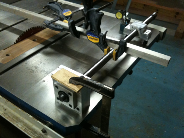
To change the amount of movement to as small as possible there is a 6 ft length of Aluminium tube clamped to the ball screw, just rocking the end of the aluminium tube up and down slightly produces same movement on the DT gauge.. This is with almost no load, no doubt it will be different in practice when some force is applied. Backlash is too small to be measurable, (the DT gauge has 0.01mm divisions)
Hi Rod,
Thanks for the info on the pendant setup. I haven't decided on the control panel layout, but I can see where a pendant would be the perfect solution. I'm slowly coming around the the view that handwheels aren't needed.
Regards
Ray
-
17th May 2010, 11:43 PM #105
GOLD MEMBER
- Join Date
- May 2003
- Location
- Perth WA
- Posts
- 3,784
Hi Ray,
Sorry I am going to pick your brains a bit here. Do you have the bearings loaded inwards - towards each other or outwards. What are you using to shim between the bearings - are you making your own from shim material or buying ready made ones for bearings and if so where did you pick them up from?
Good to hear you got over your lathe problem without too much bother.
To test the backlash you really need a load on the ballnut as the nylon sweepers being new are probably holding the nut with no load. Perhaps you could hang a weight over the table and tie it to your ballnut.Cheers,
Rod


Similar Threads
-
Hafco Hm52 on the fritz again
By Retromilling in forum METALWORK FORUMReplies: 25Last Post: 12th August 2009, 11:14 AM -
CNC conversion
By sonic_racing in forum METALWORK FORUMReplies: 7Last Post: 18th January 2009, 03:11 PM -
PSI conversion
By dmassey31 in forum WOODTURNING - PEN TURNINGReplies: 2Last Post: 26th November 2006, 09:03 AM -
Conversion of 3ph to 1ph
By MikeK in forum WOODWORK - GENERALReplies: 4Last Post: 2nd November 2005, 03:51 PM
