

 Thanks:
  Likes:
  Needs Pictures:
  Picture(s) thanks:
Results 106 to 120 of 183
Thread: HM52 CNC Conversion
-
18th May 2010, 12:14 AM #106
 GOLD MEMBER


- Join Date
- Jun 2008
- Location
- Victoria, Australia
- Age
- 74
- Posts
- 6,132

Hi Rod,
Yes, it really need a load to test it properly, I can simulate a load of sorts by clamping the ballnut to the table, made no difference to the results.
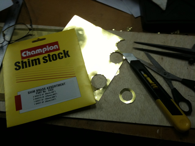
With the VXB bearings, have a look at the inner races, on one side they are larger diameter, these sides go towards each other, when I do that and clamp them up the outer races are touching, but the inner races are loose. So the shims go on the inside between the center races. If you clamp them up and the inner races are touching and the outer race is loose, then swap them around and shim between the outer races. Sounds confusing I know. It's easier than it sounds.
Nothing fancy about the shims, I just cut them from standard shim stock, with scissors and a stanley knife, I tried a wad punch, but caused too much distortion. The standard shim pack didn't have 1 thou, I had to buy that seperately. After cutting out, I smoothed and flattened the edges with the back of the knife so you don't get little bits folded over.
Regards
Ray
-
18th May 2010 12:14 AM # ADSGoogle Adsense Advertisement
- Join Date
- Always
- Location
- Advertising world
- Age
- 2010
- Posts
- Many
-
18th May 2010, 01:38 AM #107
GOLD MEMBER
- Join Date
- May 2003
- Location
- Perth WA
- Posts
- 3,784
Thanks Ray
It makes sense as you want to push the inner race into the ball groove. Being angular contacts the ball groove is on an angle to one side of the bearing.
I have had similar problems cutting shim washers with wad punches that is why I asked.
Good thinking, clamping the nut will give you a good indication of backlash with a load.Cheers,
Rod
-
18th May 2010, 01:46 AM #108
GOLD MEMBER
- Join Date
- Jun 2008
- Location
- Victoria, Australia
- Age
- 74
- Posts
- 6,132
Just to confuse you further...
 here is a sketch of the two arrangements.
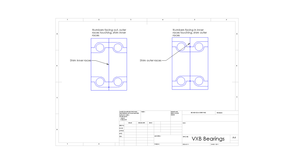
I hope that helps, there are a lot of different posts on cnczone, that are contradictory, and there appears to be no preferred way of stacking these bearings, If I've understood correctly, the higher priced AC bearings that are sold as matched pairs are marked as to which way round they go. And you can specify which way you want. Not so with these.
You can also insert spacers between the inner races as well as the outer races, and get the preload by adjusting the difference in spacer thickness.
Regards
Ray
-
18th May 2010, 02:39 AM #109
GOLD MEMBER
- Join Date
- May 2003
- Location
- Perth WA
- Posts
- 3,784
Thanks Ray that does help.
I have read a lot on the zone about bearings and get lost in their technical jargon but your drawing is much easier for me to follow.
The internal structure of the bearing is not what I imagined so that has been helpful too.Cheers,
Rod
-
18th May 2010, 04:24 PM #110
GOLD MEMBER
- Join Date
- Jun 2008
- Location
- Victoria, Australia
- Age
- 74
- Posts
- 6,132
Making the servo mounting plate.
This is made from some 1/2" 6061 Aluminium.
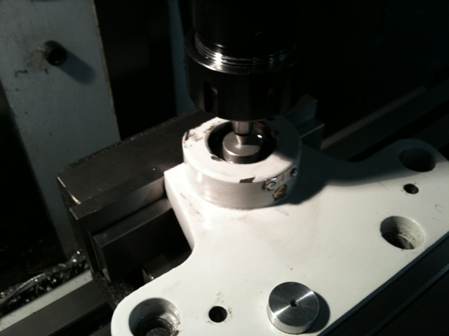
Using the DRO to digitize the hole positions, with a center finder and some
Aluminium plugs turned to fit the holes that were too big for the center finder.
Test Plate made from acrylic sheet, to confirm the hole locations, it took two goes to get it right.
Test fitting the half finished plate, the bottom section will be cut down to a taper down the suit the servo.
The four holes around the shaft are for mounting the bearing block. Once the final position is fixed I will drill new
dowell pin holes to locate the plate. Can't see any other way to do it.
Most of the machining done by my son Josh, (this is a joint project).
The ER32 collets arrived from CTC, very nice, the difference in finish between drilling a hole using a jacobs chuck and a collet is amazing.
Can't wait to see the X-axis move under servo control... getting a little closer each day.
Regards
Ray
-
18th May 2010, 07:49 PM #111Dave J Guest
Moving along nicely Ray.
Dave
-
20th May 2010, 09:31 PM #112
GOLD MEMBER
- Join Date
- Jun 2008
- Location
- Victoria, Australia
- Age
- 74
- Posts
- 6,132
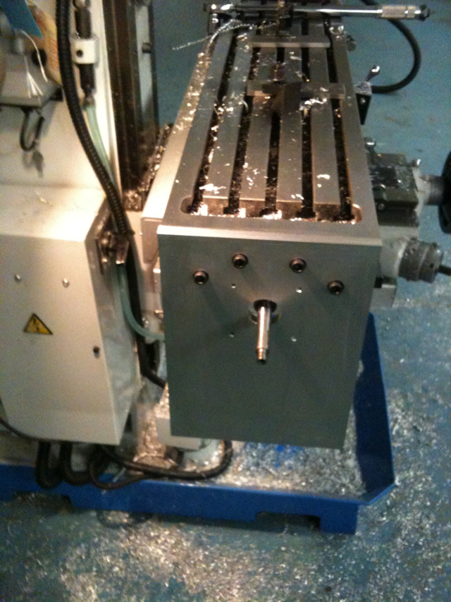
The X-axis conversion continued,
The final design, is something like this, the width is the same as the width of the table, and the drive belts and pulleys are fully enclosed.
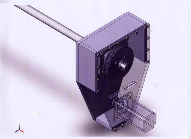
So far Josh has made everything except the plate that goes on the front which mounts the servo. We won't do that until the belts and pulleys arrive, so we can be sure the position of the servo is correct, also since the servo is fixed we are using idlers to adjust the belt tension, and we need two because the belt runs both ways.
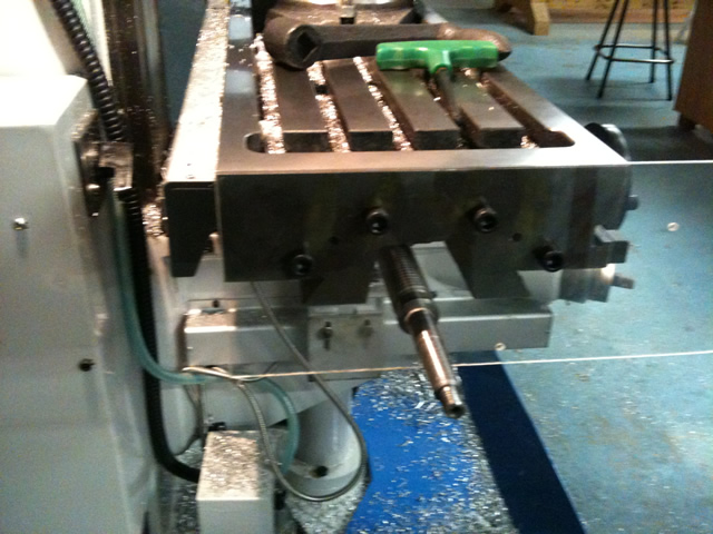
Here is the main part of the x-axis drive enclosure.
And a view from the other side,
The lower portion of the sides are perspex, so you can see inside. To make sure the belt is running properly etc...
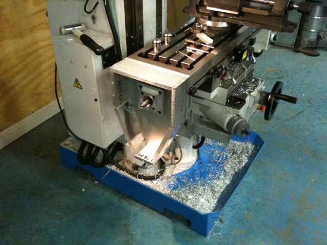
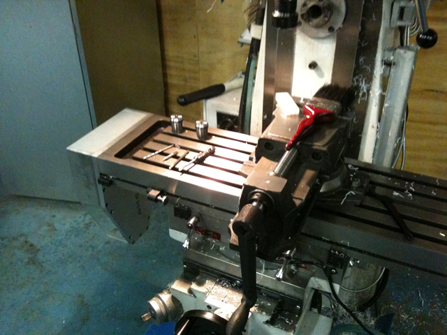
The next job is to machine the ballscrew ends, now that we can get the final dimensions. After that it's time to pull the table off and machine the ballnut mounting , at that stage we will be running the x-axis with ballscrews, no servo control yet..... but almost...
Credit for the machining goes to my son Josh who has done an outstanding job.. One day, I might get to have a go too...
Regards
Ray
-
21st May 2010, 09:54 PM #113
GOLD MEMBER
- Join Date
- Jun 2008
- Location
- Victoria, Australia
- Age
- 74
- Posts
- 6,132
With the x axis conversion well under way, the y-axis will be done in similar fashion, it's time to start thinking about how to tackle the z-axis.
As discussed earlier, the decision is to drive the quill rather than the knee, here is a sketch of the general concept.
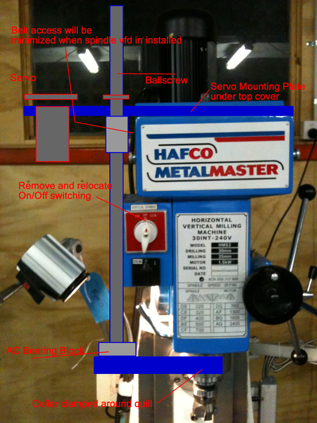
The electrical switch box will be removed, a plate made to fit the top of the spindle cover. A thick (3in thick?) close fitting collar will be clamped to the quill and the support for the AC bearings machined into the collar. It's important (I think) to make this assembly as rigid as possible as this is a point where any flex will affect the accuracy, also getting the axis of the ballscrew as close as possible to the axis of the quill will reduce flex.
The servo and ballnut will be mounted at the top allowing the ballscrew to extend above the servo plate when the quill is in the fully up position.
The ballscrew and servo mount will prevent access to the belt drive from the left hand side, you can still get at the belts from the right hand side, although with the conversion of the spindle drive to vfd, i don;t think I'll need to get to the belts as often.
The access to the tramming bolts is unchanged, and quill travel will be unchanged.
Still pondering the options....
Regards
Ray
-
22nd May 2010, 12:15 AM #114Dave J Guest
Hi Ray,
Just thought I'd through in some other options.
I have thought out the quill drive a bit and my idea is to drive the nut. That would let the screw to be mounted solid into the lower quill block which would help stop flexing.
The nut bearing housing could be mounted closer in where the electrical box is, and the screw can run close to the top housing.
What your thoughts on going this way?
Dave
-
22nd May 2010, 12:53 AM #115
GOLD MEMBER
- Join Date
- Jun 2008
- Location
- Victoria, Australia
- Age
- 74
- Posts
- 6,132
Hi Dave,
You mean like this?
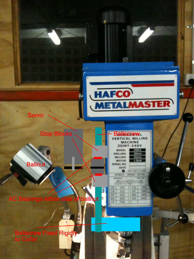
The electrical box was removed with a bit of digital magic, the big advantage of that method would be the ballscrew axis could be a lot closer to the spindle axis.
Did I understand you correctly?
Regards
Ray
-
22nd May 2010, 02:06 AM #116Dave J Guest
Hi Ray,
Yes, that is the type of setup I am talking about. The limiting factor for how close the screw can be to the head will be the pulley size. The nut will need to be as low as possible to get full travel of the quill other wise the screw will need to go higher.
The bearing block would not need to be much longer than the ball nut, you just need get bearings a bit bigger than the ball nut and machine up a spacer to bolt the nut in and hold the inside of the bearings on the outside.
I plan on cncing the knee and the quill on mine, that way I can use either one for the type of job at hand. Remember without the knee cnced you can't have a cnc horizontal mill or be able to use it as a lathe like Chich has done.
Dave
-
22nd May 2010, 03:47 PM #117
GOLD MEMBER
- Join Date
- Jun 2008
- Location
- Victoria, Australia
- Age
- 74
- Posts
- 6,132
Hi Dave,
I like your quill driving method better than my first idea, the ballscrew would be nice and short which helps keep flexing down.
Not sure I understand why CNC'ing the knee helps with using the Horizontal arbour as a lathe. I was thinking you would just use XY. I can see where driving the knee would be an advantage for horizontal milling however. How are you going to drive the knee, are you going to counterbalance it?
Time to take some measurements and draw up the Z axis, I'm thinking I'll cast the part that clamps to the quill, I don't have any blocks of Al big enough.
Regards
Ray
-
22nd May 2010, 04:58 PM #118Dave J Guest
Hi Ray,
Your right about the knee in lathe mode, I think I had a late night brain malfunction.
With his high speed router design you would also need the knee driven.
I am not 100% sure on what type of counter balance but it will need one. I have been thinking of using modified air cylinder or cylinders.
I read one blokes post in Chich's thread, were the factory cnc knee had the ball screw attached to a piston and the nut was driven. I am leaning towards this idea as it would only mean removing the standard knee tube.
One thing I wont do is to cut any part of the base out. I have measured and it could be done if factory cylinder was modify on the end caps a to fit were Chich's is.
Dave
-
24th May 2010, 12:32 AM #119
GOLD MEMBER
- Join Date
- Jun 2008
- Location
- Victoria, Australia
- Age
- 74
- Posts
- 6,132
On reflection I think it's a good idea to drive both, but driving the knee is by far more tricky to get right, with base/column flexing issues, counter weight vs gas strut and so on. That said, there may be hidden gotcha's in driving the quill of course Originally Posted by Dave J
 ..
..
Only one way to find out.
I finished machining the x-axis ballscrew tonight. No pictures yet, took pretty much all weekend, about 1 day per ballscrew end. Now I have fingers crossed I got all the measurements right.
There is a new thread over on cnczone you might be interested in... a King Rich KRV2000 cnc conversion. Nice looking machine..
Build Thread King Rich KRV-2000 Knee Mill CNC Conversion - CNCzone.com-The Largest Machinist Community on the net!
Regards
Ray
-
24th May 2010, 01:00 AM #120Dave J Guest
Hi Ray,
I will keep my eye on that conversion as well, it's a nice machine.
Sounds like you have been busy all weekend machining. Going by the work I have seen you do, I think they will turn out right.
Dave


Similar Threads
-
Hafco Hm52 on the fritz again
By Retromilling in forum METALWORK FORUMReplies: 25Last Post: 12th August 2009, 11:14 AM -
CNC conversion
By sonic_racing in forum METALWORK FORUMReplies: 7Last Post: 18th January 2009, 03:11 PM -
PSI conversion
By dmassey31 in forum WOODTURNING - PEN TURNINGReplies: 2Last Post: 26th November 2006, 09:03 AM -
Conversion of 3ph to 1ph
By MikeK in forum WOODWORK - GENERALReplies: 4Last Post: 2nd November 2005, 03:51 PM
