

 Thanks:
  Likes:
  Needs Pictures:
  Picture(s) thanks:
Results 121 to 135 of 183
Thread: HM52 CNC Conversion
-
25th May 2010, 10:44 PM #121
 GOLD MEMBER


- Join Date
- Jun 2008
- Location
- Victoria, Australia
- Age
- 74
- Posts
- 6,132

Slight delay in the CNC conversion project, the lathe is out of commission, the lead screw drive gearbox made a loud clunking sound and the leadscrew stopped, the nylon idler gear stripped and the selector lever casting snapped.
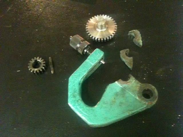
No other damage that I can see.
I suspect the casting was already cracked at the top of the bearing, it's very thin at that point and appeared to have been ground away for extra clearance. When it let go the shaft dropped and jammed the gears causing the nylon idler to strip.
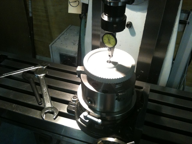
We have re-toothed the idler, using the mill with rotary table and fly cutter, to re-cut it a slightly smaller diameter, and a few less teeth.. and now we are busy fabricating a replacement for the broken casting.
Never rains...
Regards
Ray
-
25th May 2010 10:44 PM # ADSGoogle Adsense Advertisement
- Join Date
- Always
- Location
- Advertising world
- Age
- 2010
- Posts
- Many
-
26th May 2010, 03:15 AM #122
GOLD MEMBER
- Join Date
- May 2003
- Location
- Perth WA
- Posts
- 3,784
Ray,
Sorry to hear Murphy's visited on the weekend.
Repair looking good so far and hope it works out for you.
Was there two AL330 models as mine has a geared drive with rotary selection where that looks like a Norton style lever.Cheers,
Rod
-
26th May 2010, 08:32 AM #123
GOLD MEMBER
- Join Date
- Jul 2006
- Location
- Adelaide
- Posts
- 2,680
 Originally Posted by RayG

My brain cant picture that
How does one do that....cut straight teeth on a round disc of metal with a fly cutter ....isnt the cutter going circular????
Ah!....think I just figured it out
the cutter is not being used as you would use a face type mill...but rather as radial (if thats the word) cutter
-
26th May 2010, 11:32 PM #124
GOLD MEMBER
- Join Date
- Jun 2008
- Location
- Victoria, Australia
- Age
- 74
- Posts
- 6,132
Hi Eskimo,
The fly cutter is ground to the tooth profile, this one is made from a piece of 1" shaft turned down to fit a 20mm ER32 collet, the cutter is ground from the shank of an 8mm drill bit, and then that's held in place with a couple of 5mm cap screws. The profile is ground close to the profile on the wheel, and then finished off with a dremel, by test fitting and holding up to the light. The gear being cut is held vertically on a three jaw chuck bolted to the rotary table (mounted vertically) (EDIT: I MEANT HORIZONTAL )and then the indexing wheel is set up to whatever number of teeth you require. I should have taken some pictures...
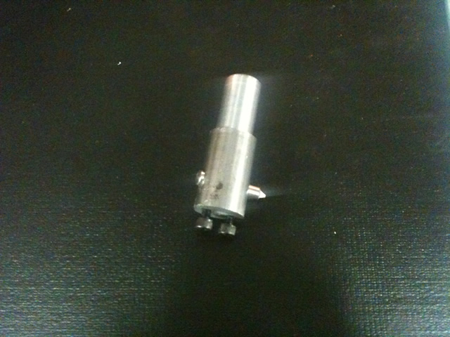
Sorry about the blurry photo..
The Lathe is now back up and running.
Here is the replacement selector lever.

The replacement selector arm was made from 3 pieces of Aluminium plate cut out on the bandsaw, bolted together and filed and linished to shape. The holes for the shaft were bored on the mill. I will still go ahead and buy the spare part (when I can find out what the part number is !) meantime this one works nicely.
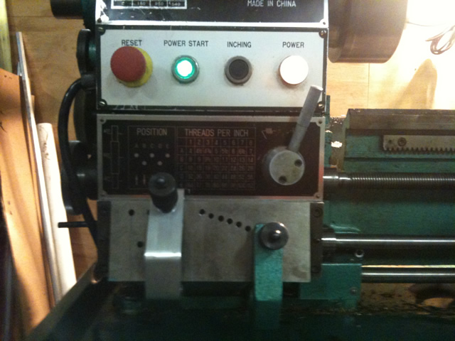
Here is the part finally installed and running....
Regards
Ray
-
27th May 2010, 12:06 AM #125
GOLD MEMBER
- Join Date
- Jun 2008
- Location
- Victoria, Australia
- Age
- 74
- Posts
- 6,132
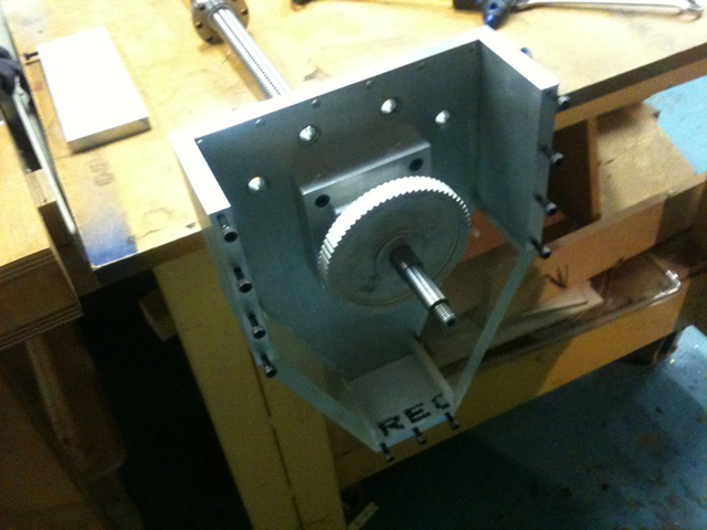
After the lathe hassles, it's good to get back to the conversion project, the timing gears and belts have arrived, they were from this supplier... Mechanical Components Timing Belts Pulleys Spur Gears Pulley Couplings Bearings Brakes Gear Clutches Shafts Shaftloc Sprockets Retaining Rings Fairloc ConiDrive Manufacturing The local suppliers quoted ridiculous prices and didn't return phone calls, etc... In the end I bought exactly what I wanted on line and they turned up a few days later..
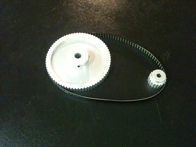
The reduction is 4:1 The servo is 18 teeth and the ballscrew 72 teeth.
The 4:1 reduction should give me 180 x 4 = 720 oz-in and peak torque of 2160 oz-in
The motor is rated at 3000 rpm, so that is 750 rpm on the ballscrew, or 12.5 revs per second, times the pitch (5mm) equals 62.5 mm/sec or 147 ipm.
Here is the setup for boring to suit the shafts.
And first trial fit.
The next job is to determine the final locations for the front panel which holds the servo.
Regards
Ray
-
27th May 2010, 08:56 AM #126
GOLD MEMBER
- Join Date
- Jul 2006
- Location
- Adelaide
- Posts
- 2,680
Ta Ray...?i think
"The gear being cut is held vertically on a three jaw chuck bolted to the rotary table (mounted vertically) and then the indexing wheel is set up to whatever number of teeth you require. I should have taken some pictures..."??? you should have....hahaha
I am having trouble picturing that, how you used indexing to cut a gear (then proceed to the next one etc etc), while the gear is held vertically with a cutter running horizontally in a circular motion ...
I need a big thinking cap
-
27th May 2010, 09:28 AM #127
GOLD MEMBER
- Join Date
- Jun 2007
- Location
- sydney
- Age
- 64
- Posts
- 3,566
Judgeing by the method described I would say that his Cutter is held in the Horizontal Spindle.
The Rotary table would need to be running true.
The Gear Blank would be set so the Centre of it was on the same Centre as the Cutter.
Not sure if the Teeth would of been cut in 1 or 2 or more passes.
Depth of cut would of been taken with the Z axis.
The Knee would of been raised and lowered to perform the cut.
If the cut had been done in one go the Cutter may have been raised back through the cut tooth and then the Rotary table indexed the correct number of degrees.
The cutter may have been left at the finished side of the Gear,Table rotated and a cut taken with the Knee in the opposite direction.
If the cuts were done in stages they may have been done to finish 1 tooth at a time or the Gear may have been rotated each time untill the finished cut was taken.
This is only my guess as to how it was done with the information given.
-
27th May 2010, 10:10 AM #128
GOLD MEMBER
- Join Date
- Jul 2006
- Location
- Adelaide
- Posts
- 2,680
Pipeclay......ta...but now i am in a state of information overload
The cutter tool holder is in the horizontal plane with the cutter in the radial plane of that.
The gear is held vertically in a 3 jaw chuck on a rotary table mounted vertically
so that means the rotary table when rotated goes around on the horizontal plane
and you cut each tooth by indexing the table....
?????
I really do need a picture....video would be good
-
27th May 2010, 10:30 AM #129
GOLD MEMBER
- Join Date
- Jun 2007
- Location
- sydney
- Age
- 64
- Posts
- 3,566
What part are you having trouble understanding?
Can you understand how it would be done with the vertical spindle?
This is cutting a group of 127 tooth gears in the Vertical,just imagine it on its side for Horizontal,but without the Tailstock.
-
27th May 2010, 10:59 AM #130
GOLD MEMBER
- Join Date
- Jul 2006
- Location
- Adelaide
- Posts
- 2,680
Thanks pipeclay
i quote Ray "rotary table (mounted vertically)"
so the rotary table was mounted horizontal and not vertically as Ray said above
-
27th May 2010, 11:18 AM #131
GOLD MEMBER
- Join Date
- Jun 2007
- Location
- sydney
- Age
- 64
- Posts
- 3,566
No, his table would of been Vertical,his Cutter would of been Horizontal.
His blank would of been mounted the same way as his 72 tooth gear is mounted in his CNC conversion.
With his cutter in the Horizontal Spindle he would just bring the Gear blank into the Depth of cut he required then just raise and lower his table.
-
27th May 2010, 11:44 AM #132
GOLD MEMBER
- Join Date
- Jul 2006
- Location
- Adelaide
- Posts
- 2,680
I'm getting there ...hahaha
so the cutter would have come in from either end (the side) of the table
-
27th May 2010, 12:41 PM #133
GOLD MEMBER
- Join Date
- Jun 2007
- Location
- sydney
- Age
- 64
- Posts
- 3,566
The Cutter would not move,the Gear Blank would be set at the Centre of the Cutting Tool and the Gear Blank would be moved towards the Cutter for Depth of Cut, and then the Table would be Raised to perform the Cut.
-
27th May 2010, 03:02 PM #134Dave J Guest
Eskimo,
This might help you. Reg lives around the corner from me.
gearcutting
Dave
-
27th May 2010, 05:22 PM #135
GOLD MEMBER
- Join Date
- Jul 2006
- Location
- Adelaide
- Posts
- 2,680
ah ah got it
a couple of pics does wonders for my brain...same as looking at a pic of jenifer hawkins, but only different
thanks guys
Reg has some great stuff there!!Last edited by eskimo; 27th May 2010 at 06:02 PM. Reason: comment on Reg


Similar Threads
-
Hafco Hm52 on the fritz again
By Retromilling in forum METALWORK FORUMReplies: 25Last Post: 12th August 2009, 11:14 AM -
CNC conversion
By sonic_racing in forum METALWORK FORUMReplies: 7Last Post: 18th January 2009, 03:11 PM -
PSI conversion
By dmassey31 in forum WOODTURNING - PEN TURNINGReplies: 2Last Post: 26th November 2006, 09:03 AM -
Conversion of 3ph to 1ph
By MikeK in forum WOODWORK - GENERALReplies: 4Last Post: 2nd November 2005, 03:51 PM
