

 Thanks: 0
 Likes:
  Needs Pictures: 0
 Picture(s) thanks: 0
Results 1 to 15 of 25
-
30th October 2013, 09:43 AM #1
 Senior Member


- Join Date
- Apr 2008
- Location
- NSW
- Posts
- 356
 Sine bar setting taper attachment
I need help with a concept . I want to build a taper attachment to fit an Al 1000c lathe .
I don't want to set it with graduations of any kind as I just can't see them well enough and they are just not accurate enough.
I use a small sine bar setting gauge on my compound for short tapers and for me it's perfect as I have small programs that work out the taper and stack height and I can just apply that stack height and I'm set to go. No squinting at graduations hidden in the shadows .
I want to use the programs I have already and just apply the same stack height data to the longer taper attachment .
I am not good at drawing plans . I have a mind concept but if it will help anyone help me then I could draw a rough sketch up of what I am thinking and others could pull it apart and suggest better ways keeping in mind I want to keep it simple to make .
My concept is a round bar able to slide in slots and lockable at both ends . The heads of the bar like a tie rod machined to the exact same diameter so they present two roll type surfaces like a sine bar .
The place I am stuck is coming up with a gauge system to zero one end from the centre of the lathe and allow applying the stack height to the other end from the lathe centre. Both ends of the bar may need to be moved to get certain angles and that would vary the distance from the lathe centre .
All I can think is that the two setting gauges would need to be adjustable in and out and be set the same each time but that would mean that one end of the bar may have a big stack height of several inches which would could be outside the capabilities of a gauge block set .
I may be possible to set the stack height difference on one of the setting gauges rather than use blocks with a mike or digital calliper and still be more accurate than graduations .
If I have a sample taper I can mount it then I could set the bar with a dial gauge but I don't always have a sample taper .
I hope I am explaining this ok and someone is following all this .
Any input would be appreciated .The volume of a pizza of thickness 'a' and radius 'z' is given by pi z z a.
-
30th October 2013 09:43 AM # ADSGoogle Adsense Advertisement
- Join Date
- Always
- Location
- Advertising world
- Posts
- Many
-
30th October 2013, 08:09 PM #2
Senior Member
- Join Date
- Apr 2008
- Location
- NSW
- Posts
- 356
Anybody ? 59 views and no one
 The volume of a pizza of thickness 'a' and radius 'z' is given by pi z z a.
-
30th October 2013, 08:42 PM #3
Blacksmith, Cabinetmaker, Machinist, Messmaker
- Join Date
- Dec 2011
- Location
- Canberra
- Age
- 40
- Posts
- 4,467
Hi Retro,
I did mean to reply last night.....it didn't happen!
What sort of TTA will you be making? Round guide rail or machined square/dovetail? I would simply suggest using your sine bar and blocks on the guide rail, that way your stack shouldn't be too high at larger angles.
I'd be interested to see which way you go, i'd like to make one for the Antrac.
Cheers,
Ew1915 17"x50" LeBlond heavy duty Lathe, 24" Queen city shaper, 1970's G Vernier FV.3.TO Universal Mill, 1958 Blohm HFS 6 surface grinder, 1942 Rivett 715 Lathe, 14"x40" Antrac Lathe, Startrite H225 Bandsaw, 1949 Hercus Camelback Drill press, 1947 Holbrook C10 Lathe.
-
30th October 2013, 08:45 PM #4
SENIOR MEMBER
- Join Date
- Oct 2012
- Location
- Australia
- Posts
- 765
Are you thinking something like the Sinuskator?
-J
-
30th October 2013, 09:01 PM #5
 Super Moderator
- Join Date
- Jan 2004
- Location
- Mackay Qld
- Posts
- 3,466
Alright, I be the one that's asks:
Whats a Sinuskator ?
Grahame
-
30th October 2013, 09:13 PM #6
SENIOR MEMBER
- Join Date
- Oct 2012
- Location
- Australia
- Posts
- 765
Basically a chuck-able sine bar Originally Posted by Grahame Collins

-
30th October 2013, 09:35 PM #7
.
- Join Date
- Nov 2008
- Location
- Perth WA
- Age
- 71
- Posts
- 5,650
Hey Josh, Originally Posted by Brobdingnagian
Any more photos to tantalise us with?
BT
-
30th October 2013, 09:58 PM #8
SENIOR MEMBER
- Join Date
- Oct 2012
- Location
- Australia
- Posts
- 765
Originally Posted by Anorak Bob
just a few more from the nets.
jahrl sinuskator 1.jpgjahrl sinuskator 2.jpgjahrl sinuskator 3.jpgjahrl sinuskator 4.jpgjahrl sinuskator 5.jpg
-
30th October 2013, 10:25 PM #9
Senior Member
- Join Date
- Apr 2008
- Location
- NSW
- Posts
- 356
I will be making a round bar guide as I can't machine a dovetail long enough Originally Posted by Ueee
in one setup .
I thought of using a sine bar right against the guide bar but the centre height is well above the TA so the only parallel centre that I can see that I can work with that's close to the TA is the bed V way . Also it's a long way from the lathe centre to the TA so it would need to be a massive sine bar to reach over . The sine bar I have is specific to setting the compound and is not suitable .
However I do get your advice on having a shorter roll distance against the guide bar to reduce stack heights .
I may be able to make a sine bar that clamps onto the back v -way and extends out to the bar with say a 6 or 8 inch roll distance .
Thanks that has given me another idea to pursue much appreciated .
The limitations I see is how far the bar can be adjusted at both ends to get bigger angles with a fixed sine bar .
I will do a sketch of what I am planning when I get a better idea of what will work .The volume of a pizza of thickness 'a' and radius 'z' is given by pi z z a.
-
30th October 2013, 10:28 PM #10
Senior Member
- Join Date
- Apr 2008
- Location
- NSW
- Posts
- 356
The principls are the same but it's a long way from the lathe centers to the Taper Attachment so it's going to be a different setup but same sine bar principle. Originally Posted by Brobdingnagian
The volume of a pizza of thickness 'a' and radius 'z' is given by pi z z a.
-
30th October 2013, 10:29 PM #11
.
- Join Date
- Nov 2008
- Location
- Perth WA
- Age
- 71
- Posts
- 5,650
Ew ,
I reckon the Mini-Sine would work well enough. Fixed it yet?
BT
-
30th October 2013, 11:04 PM #12
Senior Member
- Join Date
- Feb 2013
- Location
- Laidley, SE Qld
- Posts
- 368
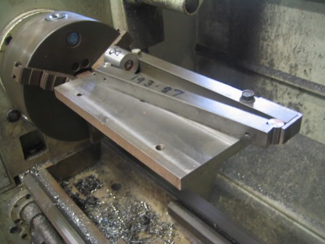
I made myself a chuck mounted sine bar a while ago, its a very useful piece of kit, and simple to make. Not my idea, I saw it on Practical Machinist.
Piece of shafting with a plate mounted on it, fence along the back edge.
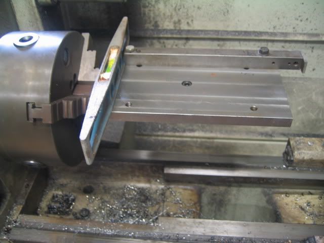
Home made sine bar. I don't have any blocks so to set the angle I turn a piece of scrap to the required diameter. I set the compound using parallels between the sine bar and the QCTP.
-
30th October 2013, 11:06 PM #13
Blacksmith, Cabinetmaker, Machinist, Messmaker
- Join Date
- Dec 2011
- Location
- Canberra
- Age
- 40
- Posts
- 4,467
Why can't you set the sine bar against the guide so you can use a dial off the saddle? You could do it with a mag base on the cross slide before you disengaged your screw etc or off the saddle itself after afterwards. I never use the tailstock quill to set the compound (my memory is a bit hazy but is this what you do-i know i remember reading about someone that does that) I always set it with a dial. Bruce (Abratool) put a pic up of a similar setup at one stage.....i'll se if i can find it. Originally Posted by Retromilling
Nearly.....Got the SS from Michael yesterday, it is ground, just needs the holes put in it. Originally Posted by Anorak Bob
Cheers,
Ew1915 17"x50" LeBlond heavy duty Lathe, 24" Queen city shaper, 1970's G Vernier FV.3.TO Universal Mill, 1958 Blohm HFS 6 surface grinder, 1942 Rivett 715 Lathe, 14"x40" Antrac Lathe, Startrite H225 Bandsaw, 1949 Hercus Camelback Drill press, 1947 Holbrook C10 Lathe.
-
31st October 2013, 08:54 PM #14
Senior Member
- Join Date
- Apr 2008
- Location
- NSW
- Posts
- 356
Yes I set my compound two ways , against the tail stock quill or against a bar between centres . If you already have a job in the lathe and you need to change angles then I use the tail stock quill or the job it's self if it has a parallel section big enough . The compound sides run very true to the dovetails and the tail stock is right on centre across ways so there is not a big error . I make Nt 30 milling arbours and they fit well with less run out than a couple I have bought . So the system works well enough. Originally Posted by Ueee
Made an NT 30 to Morse 5 adaptor for the lathe spindle using this system and it fits real good.
I will have to think about what you have said and see if it will work for me . Thanks for the input.
I have not done much as I have been battling with spread sheets for Taper calculations and Sine bar stack heights . The two programs I have don't run on my new shed laptop , as it's windows 8 so I have to convert to Excel spread sheets .
Nearly drove me nuts but I did it . However there is a slight difference in the value of the Included angle in the Taper calculation when compared back to my old DOS based program . It's only about 2000 'ths of a degree but the funny thing is the spread sheet compares exactly to the scientific calculator using Atan function but the DOS program I have compares exactly to some online calculators . I have cut all my tapers using the DOS program and it's worked ok so far . I tried every trig function to try and reproduce the value of the DOS program but nothing was closer than the Atan ( ArcTan ) function So it's got me stuffed which is right. That's why I hate math it's too annoying .
The sine bar spread sheet is bang on with everything .The volume of a pizza of thickness 'a' and radius 'z' is given by pi z z a.
-
31st October 2013, 09:19 PM #15
SENIOR MEMBER
- Join Date
- Oct 2012
- Location
- Australia
- Posts
- 765
sounds like a rounding error. turn up the precision in your spreadsheet for accurate calculations. Originally Posted by Retromilling
-J


Similar Threads
-
Hercus taper turning attachment
By 4-6-4 in forum THE HERCUS AREAReplies: 0Last Post: 7th December 2011, 07:25 PM -
Taper Turning Attachment
By Garry Edwards in forum THE HERCUS AREAReplies: 45Last Post: 26th April 2011, 10:20 PM -
Taper Attachment casting photos
By Swarfmaker1 in forum THE HERCUS AREAReplies: 2Last Post: 10th January 2011, 08:28 PM -
Taper Turning Attachment Installation
By Rodd Perrin in forum THE HERCUS AREAReplies: 8Last Post: 18th April 2010, 08:50 AM -
Looking for a Taper turning attachment
By aljunk in forum THE HERCUS AREAReplies: 10Last Post: 27th December 2008, 11:47 PM
