

 Thanks: 0
 Likes: 0
 Needs Pictures: 0
 Picture(s) thanks: 0
Results 16 to 30 of 34
Thread: Star/Delta motor wiring
-
29th February 2012, 03:14 PM #16
 Pink 10EE owner


- Join Date
- Aug 2008
- Location
- near Rockhampton
- Posts
- 4,304

I got some Vinidex abrasion/heat resistant sleeving at Jaycar today, should be right to wire it up when I get some time now...
Light red, the colour of choice for the discerning man.
-
29th February 2012 03:14 PM # ADSGoogle Adsense Advertisement
- Join Date
- Always
- Location
- Advertising world
- Posts
- Many
-
29th February 2012, 05:09 PM #17
GOLD MEMBER
- Join Date
- Jun 2008
- Location
- Victoria, Australia
- Age
- 74
- Posts
- 6,132
Hi .RC,
I could have got some for you earlier today, there is a special hi-dielectric heat resistant varnish they use in rewinding as well. It's not the sort of thing you need a lot of, but I don't think it comes in small containers. I could get some if you like.
Old wiring can be fragile, so make sure to double check everything. I know you will, but doesn't hurt to mention it anyway.
Regards
Ray
-
29th February 2012, 06:20 PM #18
Pink 10EE owner
- Join Date
- Aug 2008
- Location
- near Rockhampton
- Posts
- 4,304
Thanks Ray, I probably do not need any varnish at this stage...
Just one question, I have soldered the wires onto the windings wires, I guess putting heat shrink tubing over the top over the soldered joins and the heat resistant tubing over the top of that is not the way to go? And just use the heat resistant tubing on it's own?
The wiring on this grinder is OK... The machine was made in the 90's..Light red, the colour of choice for the discerning man.
-
29th February 2012, 07:57 PM #19
GOLD MEMBER
- Join Date
- Jun 2008
- Location
- Victoria, Australia
- Age
- 74
- Posts
- 6,132
Hi RC,
You don't need heatshrink, the wire insulation is probably class 180 (rated to 180 C), the termination procedure is to push on the smaller diameter heat resistant tubing, nice fit to the wire, then cover with a piece of larger diameter tubing and tie it down neatly, make the splice nice and smooth and not too lumpy.. when you do the solder joint make sure you get the insulating varnish off the magnet wire, and tin the ends before joining and finally soldering.
EDIT.. when you tie it down, make it so the join isn't under strain.... that is tied both sides.... bit hard to describe in words, but I think you've got the idea.
Regards
Ray
-
29th February 2012, 09:45 PM #20
GOLD MEMBER
- Join Date
- Jun 2008
- Location
- Victoria, Australia
- Age
- 74
- Posts
- 6,132
Hi .RC,
One more thing...
For tying the cabling down, see if you can get some of the proper lacing cord.
Search for "stator lacing cord"
Regards
Ray
-
29th February 2012, 10:26 PM #21
Pink 10EE owner
- Join Date
- Aug 2008
- Location
- near Rockhampton
- Posts
- 4,304
I had a play this evening, but the mosquitos started to carry me outside so I left them to it...
It is probably satisfactory but I am not 100% happy with it in so far that the plastic coated hook up wire I used (recycled out of a modern washing machine so I know the insulation was rated for 240+V) is in contact with the windings for part of the way.... Although in saying that the existing windings that I never touched had the plastic coated hook up wire touching the windings anyway...
I tied it all up with cotton string, recycled out of a new seed bag... it is that string they use in the big sewing machines that sew up bags.... it is quite strong and would appear to be pure cotton...
How do I identify the U, W and V wires so it is hooked up correctly....
From looking at it the coil tappings are directly opposite from one another...So if you identify one wire, the other end of that coil is the wire that is directly opposite.. Of course the windings are spaced 120 degrees apart...Light red, the colour of choice for the discerning man.
-
29th February 2012, 11:00 PM #22
GOLD MEMBER
- Join Date
- Jun 2008
- Location
- Victoria, Australia
- Age
- 74
- Posts
- 6,132
Hi RC,
Pick a wire and label it U1, using the multimeter find the other end of that coil and label it U2, pick the next wire around and label it V1, use the multimeter again to find the other end and label it V2, next one around label it W1, find the other end and label it W2.
If you have 6 terminals bring the wires out so that looking across the terminals the first row reads
U2 V2 W2
second row reads
V1 W1 U1
Now you can connect it as delta by connecting U2 to V1 ...V2 to W1 .. W2 to U1 by just linking straight across the terminal block to make it 240V delta.
Your three phase power U V W is connected to U1, V1, W1 as normal.
Regards
Ray
PS Cotton should be fine, not so sure about the PVC temperature rating, also I think it goes brittle over time, but it looks to be well supported..
-
1st March 2012, 09:42 PM #23
Pink 10EE owner
- Join Date
- Aug 2008
- Location
- near Rockhampton
- Posts
- 4,304
I need some clarification there please Ray...
I have identified each coil, where each coil is connected I just need to identify the U, V, and W points..
When you say "Pick a wire and label it U1, using the multimeter find the other end of that coil and label it U2, pick the next wire around and label it V1"
Do you mean exactly like that.... As shown in picture one... The first wire I pick is U1 then moving clockwise 60 degrees the next wire is V1 and move clockwise another 60 degrees and that wire is W1.
I am not sure if it matters but I was thinking if the coils are not wired correctly when it might not create the correct magnetic field with on say one of the fields the north/south are pointing the wrong way...
Or is it like in picture two... I find the wire U1, then move clockwise 120 degrees and find V1 and another 120 degrees and find W1.
With the corresponding U2, V2 and W2 directly opposite in both cases... To wire this motor to wye or star configuration it is like the second picture.. U2, V2 and W2 were out to the terminal block, while U1, V1 and W1 were joined together...
I have changed my wiring as well, it is now mostly covered with protective sleeving...
Light red, the colour of choice for the discerning man.
-
1st March 2012, 11:06 PM #24
SENIOR MEMBER
- Join Date
- Mar 2010
- Location
- Nth Qld
- Posts
- 715
RC, it's not at all critical which way it's wired except for two conditions:
1. Each of the wires is connected together with a wire from a different winding and then to a line phase. So you have three pairs of two winding wires connected together, and each of the pairs is connected to a line phase.
2. If it runs backwards then swap the wires of one winding only.
It's pretty much as you have labelled the wires in your photos either one would work fine.
-
1st March 2012, 11:08 PM #25
GOLD MEMBER
- Join Date
- Jun 2008
- Location
- Victoria, Australia
- Age
- 74
- Posts
- 6,132
Hi RC,
I would do it like the fist picture, the north south alternating is done when the motor is wound, that is alternating polarity every second pole. If you swap the windings over it will just run backwards...
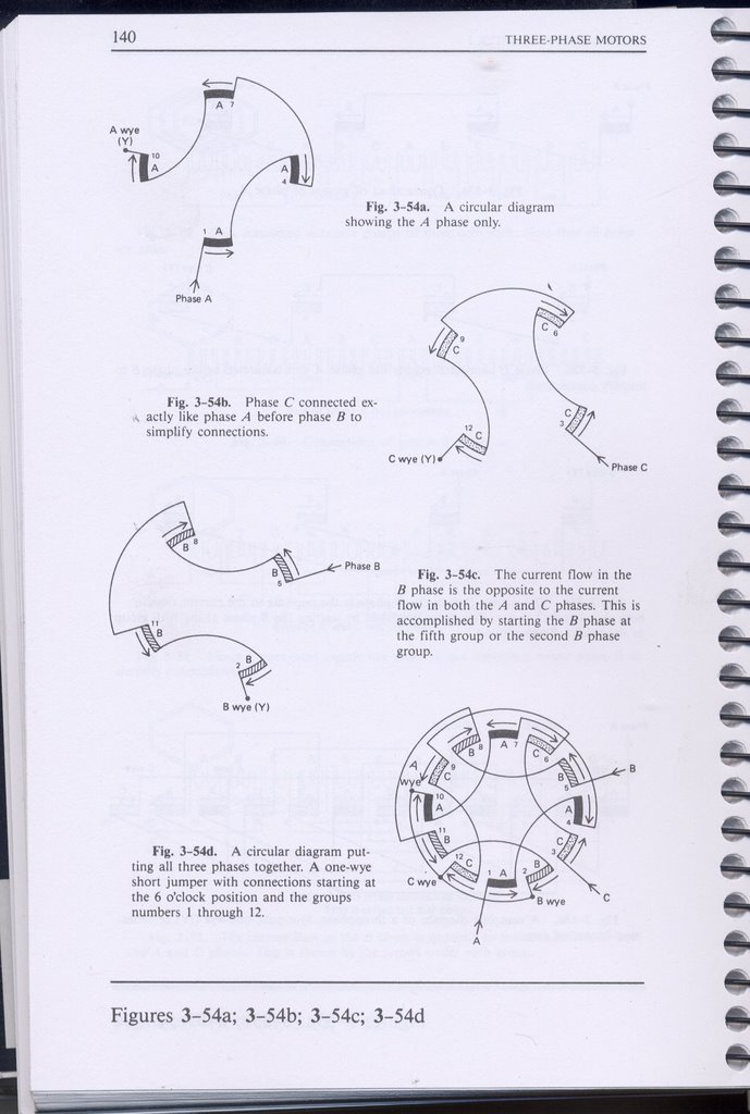
Here's a better diagram of a 3 phase 4 pole motor. This is from Rosenberg. Note that he is labelling the windings anti-clockwise, but that doesn't make any difference.
So, I hope that clarifies the issue... wire it up like your first picture, if it runs backwards, swap 2 phases, (pick any two).
Bring all six wires out to the terminal block so that you can choose star or delta at the terminal block, as already discussed. If you had a megger tester, this would be a good time to megger test the insulation.
In the absence of a megger, I would still double check that you don't have any shorts between any of the windings and ground, and no shorts between windings.
Regards
Ray
-
2nd March 2012, 07:21 AM #26
Pink 10EE owner
- Join Date
- Aug 2008
- Location
- near Rockhampton
- Posts
- 4,304
Hi Ray, This is a two pole motor it runs at 2900rpm, I assume that makes no difference in the photo's you posted, except it has half the number of windings...
Light red, the colour of choice for the discerning man.
-
2nd March 2012, 08:38 AM #27
Senior Member
- Join Date
- Dec 2011
- Location
- South East Queensland, Australia
- Posts
- 354
An amp meter on each of your input lines will show if any phase is drawing too much current. Only run for max of a few seconds if one of the amp meters is reading substantially higher current. If incorrect connections then you have to go through connecting them in a planned change over sequence until you get all meters reading much the same.
Cheers
If I'm not right, then I'm wrong, I'll just go bend some more bananas.
-
2nd March 2012, 09:18 AM #28
Senior Member
- Join Date
- Dec 2011
- Location
- South East Queensland, Australia
- Posts
- 354
I've just sketched out a windings connection test sequence and scanned it so if you have any problem I'll post it up. Important to get the windings ends connected properly, changing the supply lines(L1, L2, L3) around doesn't change the windings ends connections.
Cheers.
If I'm not right, then I'm wrong, I'll just go bend some more bananas.
-
3rd March 2012, 12:19 PM #29
Pink 10EE owner
- Join Date
- Aug 2008
- Location
- near Rockhampton
- Posts
- 4,304
Success gentlemen..... Works like a beauty....
Light red, the colour of choice for the discerning man.
-
3rd March 2012, 03:08 PM #30
SENIOR MEMBER
- Join Date
- Mar 2010
- Location
- Nth Qld
- Posts
- 715
 Originally Posted by .RC.

Awesome, your work looked well done and now with another skill under your belt, you can keep an eye out for a secondhand Kyoritsu megger unit for future motor projects.


Similar Threads
-
Wiring a GMF 8" grinder motor
By colhu in forum GENERAL & SMALL MACHINERYReplies: 11Last Post: 13th October 2021, 07:48 PM -
Wiring of a single phase motor.
By krisfarm in forum METALWORK FORUMReplies: 27Last Post: 28th October 2010, 08:10 PM -
Have I found the star point of this motor?
By Jekyll and Hyde in forum METALWORK FORUMReplies: 9Last Post: 12th August 2010, 11:25 PM -
motor wiring diagram
By .RC. in forum METALWORK FORUMReplies: 2Last Post: 12th July 2010, 07:37 PM
