

 Thanks: 0
 Likes: 0
 Needs Pictures: 0
 Picture(s) thanks: 0
Results 31 to 45 of 53
Thread: VSD enclosure
-
18th January 2011, 11:20 PM #31
 GOLD MEMBER


- Join Date
- Jul 2010
- Location
- Melbourne
- Posts
- 7,775

Well I did some more wiring but I forgot to take any pictures so here are a couple of the (hopefully) final wiring of the VSD control for the shaper. Pretty isn't it? lol
The rely on the right switches on when the VSD output is switched to the shaper. This isolates the two speed control wires then the VSD is switched to the "other side".
The rely on the left. one side is for latching "on", the other side is the 12V control for the VSD.
Stuart
p.s. oops when I said "final wiring" I meant the final mock up. I will be cleaning it up.Last edited by Stustoys; 18th January 2011 at 11:25 PM. Reason: added p.s.
-
18th January 2011 11:20 PM # ADSGoogle Adsense Advertisement
- Join Date
- Always
- Location
- Advertising world
- Posts
- Many
-
19th January 2011, 07:46 AM #32
GOLD MEMBER
- Join Date
- Jul 2006
- Location
- Adelaide
- Posts
- 2,680
I hope so...its looks ruddy awful as it is...lol Originally Posted by Stustoys

-
19th January 2011, 09:59 PM #33
GOLD MEMBER
- Join Date
- Jul 2010
- Location
- Melbourne
- Posts
- 7,775
Better?
-
20th January 2011, 08:01 AM #34
GOLD MEMBER
- Join Date
- Jul 2006
- Location
- Adelaide
- Posts
- 2,680
Originally Posted by Stustoys

-
20th January 2011, 12:58 PM #35
GOLD MEMBER
- Join Date
- Jul 2010
- Location
- Melbourne
- Posts
- 7,775
ARGH!!!!!!!!!!!
Assume nothing!!
Finished the wiring on the shaper this morning. Upped the Max Freq on the inverter to 60Hz, set the jog speed to 50Hz. Switched from mill(with 60hz displaying on the VSD) to the shaper, 50Hz comes up just like it should. Patting myself on the back, very pleased with myself.
Then I turn the speed pot....... nothing, its overridden by the jog control. This is not what I thought would happen. I'd thought the speed control would still work up to the maximum set by the jog speed. So this set up wont work.
The new plan is this. I only have two wires and they will be switched at the machine. So the diagram of the switches isnt really correct, I'll work on it.
All pots 10k
-
20th January 2011, 01:39 PM #36
GOLD MEMBER
- Join Date
- Jul 2010
- Location
- Melbourne
- Posts
- 7,775
Ok I think this is more like it.
The replys are in the machine control boxes.
The idea of the parallel pot on the machine is that one can be set to limit the max rpm amd locked, the other is then used to varie the rpm.
Will it work??
Stuart
-
20th January 2011, 01:46 PM #37
GOLD MEMBER
- Join Date
- Jul 2006
- Location
- Adelaide
- Posts
- 2,680
Ah Ah ...I get it...if it doesnt you'll have some one else to blame and chase up for your loss...gee yor smart...lol Originally Posted by Stustoys
-
20th January 2011, 01:53 PM #38
GOLD MEMBER
- Join Date
- Jul 2006
- Location
- Adelaide
- Posts
- 2,680
Originally Posted by Stustoys
I am assuming that you have drawn the last diag as "live" on the Max Speed circuit (not the variable)......if its not alive its not going to work as when you power it up that relay will switch to what is now the NO contact and you wont have any power at the VSD......
if the former is true...you've drawn it wrong as the circuit should not be drawn as liveLast edited by eskimo; 20th January 2011 at 01:55 PM. Reason: too many thumbs..i really should have typing lessons
-
20th January 2011, 03:05 PM #39
GOLD MEMBER
- Join Date
- Jul 2010
- Location
- Melbourne
- Posts
- 7,775
Ok I see what you are saying. I've drawn it as it would be if it was pluged in and the machines were on. I'll fix it.
Done. Of course the max speed of machine A can only be lower than machine B.
-
20th January 2011, 03:08 PM #40
GOLD MEMBER
- Join Date
- Jun 2008
- Location
- Victoria, Australia
- Age
- 74
- Posts
- 6,132
Hi Stuart, Originally Posted by eskimo
No it won't work, at least not the way you want. You can't just parallel up the pots like that. You have to switch the pot wipers. I think I drew a cct earlier?
I guess eskimo get's the blame, right?
Regards
Ray
PS.. Found it, it was earlier in this thread..
-
20th January 2011, 03:16 PM #41
GOLD MEMBER
- Join Date
- Jul 2010
- Location
- Melbourne
- Posts
- 7,775
But I am switching the wipers(at least that is my intent, even if the diagram doesn't show it).
I'll draw a simpler version of what I am after.Last edited by Stustoys; 20th January 2011 at 03:27 PM. Reason: at least*
-
20th January 2011, 03:21 PM #42
GOLD MEMBER
- Join Date
- Jul 2010
- Location
- Melbourne
- Posts
- 7,775
Hows this?
P.s. I may not have been clear in my earlier post. I only have two spare wires in the cable. Otherwise I would switch all three and be done with it.Last edited by Stustoys; 20th January 2011 at 03:24 PM. Reason: added p.s.
-
20th January 2011, 03:37 PM #43
GOLD MEMBER
- Join Date
- Jul 2010
- Location
- Melbourne
- Posts
- 7,775
Assuming my idea isn't complete rubbish

I've removed one of the poles on each of the relays.
Stuart
-
20th January 2011, 03:38 PM #44
GOLD MEMBER
- Join Date
- Jun 2008
- Location
- Victoria, Australia
- Age
- 74
- Posts
- 6,132
Hi Stuart,
I've got to go out for a few hours, I'll draw a circuit for you later tonight, but I'll quickly describe what you need..
First, wire up the max speed pot across the 0-10v supply, that gives you 0-10v on the wiper of that pot. That's your maximum speed. say it's set somewhere at XX volts
Now take that 0- XX v signal and wire it across the second pot, (the wiper from the max speed pot, goes to the top of the speed pot) that gives you an adjustable 0- XX volts signal that goes to the drive...
Regards
Ray
-
20th January 2011, 05:27 PM #45
GOLD MEMBER
- Join Date
- Jul 2010
- Location
- Melbourne
- Posts
- 7,775
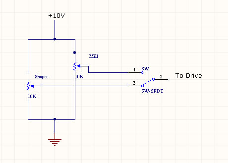
Omg I've assumed again, I thought it was the max resistance I needed to limit. I was wrong its the minimum resistance I need to limit. So here is Version 5 lol
Will this one work? I think this is part of what you mean Ray
I assume the resistance 10V-MVI being a little high wont be a problem?
I've just had another thought. I could forget the "max rpm set" and just limit the rotation of the variable rpm pot to limit rpm. Ver 6
Stuart
p.s. "simpler version of what I am after" this was of course for my benefit!


Similar Threads
-
WC2000 enclosure pics
By ozhunter in forum DUST EXTRACTIONReplies: 5Last Post: 19th December 2009, 10:34 AM -
Waldo's Dusty Enclosure
By Waldo in forum METALWORK FORUMReplies: 34Last Post: 26th November 2008, 10:49 PM -
Help needed to construct a projector enclosure
By De_Cruelz in forum WOODWORK - GENERALReplies: 19Last Post: 26th June 2005, 02:12 AM
