

 Thanks: 0
 Likes: 0
 Needs Pictures: 0
 Picture(s) thanks: 0
Results 1 to 15 of 53
Thread: VSD enclosure
-
3rd January 2011, 11:22 PM #1
 GOLD MEMBER


- Join Date
- Jul 2010
- Location
- Melbourne
- Posts
- 7,775
 VSD enclosure
Hi Guys
Here is a picture of my almost finished enclosure. This will let me switch the VSD between the 3 phase sockets on either side of the box. One socket is there, the one for the other side should turn up tomorrow. I have to wait until the 10th to get the plastic for the door. Also waiting on some 8pin din plugs so I can control pretty much all functions remotely.This will allow me to increase the max Hz limit but have the speed override set to I can lock the shaper at 50 Hz(the VSD has 3 speed limits and varible).
Lost a few hours when I checked the wiring with a DMM and found two poles of the switch weren't working. Pulled it back out thinking "how can it not work I can see the contacts". Tested it at 24VAC and it works just fine.
Haven't worked out how you work parallel speed control pots yet.
Stuart
-
3rd January 2011 11:22 PM # ADSGoogle Adsense Advertisement
- Join Date
- Always
- Location
- Advertising world
- Posts
- Many
-
4th January 2011, 12:11 AM #2
Product designer retired
- Join Date
- Nov 2006
- Location
- Heidelberg, Victoria
- Age
- 79
- Posts
- 2,251
Hi Stu.
I must join in here, and for the sake of all those unfamiliar with VFD's, ask for details about your choice. For example,
1. What voltages were involved, and HP?
2. What machine are you driving?
3. Was it easy to program?
4. Did you strike any problems, supply etc?
5. Are you happy with the final result?
6. Any tips for new comers to VFD's?
You obviously have some knowledge of electrics, judging by your photo, well done.
Will be interested to know how it all turns out.
Ken
-
4th January 2011, 01:50 AM #3
GOLD MEMBER
- Join Date
- Jul 2010
- Location
- Melbourne
- Posts
- 7,775
1. What voltages were involved, and HP?
240V single phase input(I think I said in another post somewhere that it also excepts 240V 3 phase, It doesn't, it just doesn't say that in the manual. As we cant get 240V 3 phase that I am aware, I guess that's not a problem)
415V3phase output 2.2kW 3hp
2. What machine are you driving?
So far I have used it on my mill and shaper but I will be converting my drill back to 3 phase soon. All 3hp
3. Was it easy to program?
From memory it run straight out of the box. It took me a couple of reads of the manual to work out most of the functions. I think I have only change 2 settings 1. to use remote start/stop instead of keyboard. 2. from "controlled deceleration stop" to "free run to stop". I've changed a few others while testing this and that.
4. Did you strike any problems, supply etc?
Not so far.
5. Are you happy with the final result?
Well it wont be finished for a couple of weeks I don't think, but I'm happy so far.
6. Any tips for new comers to VFD's?
Not sure one VFD qualifies me to give to many tips and I cant really think of anything much use ATM.
You obviously have some knowledge of electrics, judging by your photo, well done.
Thanks. Some knowledge can be a bad thing.
Stuart
-
4th January 2011, 05:53 AM #4
Home Hobbist
- Join Date
- Aug 2008
- Location
- Oatley NSW
- Age
- 69
- Posts
- 244
Hi Stustoys,
You may want to consider using an other Rotary Switch to bring in the two individual machine pushbutton control and speed pots.
This way you will eliminate any chance of unwanted signals from the machine which you are not useing.
Regards,
Keith.
-
4th January 2011, 09:43 AM #5
GOLD MEMBER
- Join Date
- Jul 2010
- Location
- Melbourne
- Posts
- 7,775
Hi Keith
The rotary switch I am using now has 4 poles so the 12V control is switched with the 3 phase power. I could add another 2 poles to switch the speed control I guesss, But I was planning on having a 3 speed control on the enclosure, maybe thats cant happen.
Stuart
-
4th January 2011, 11:55 AM #6
GOLD MEMBER
- Join Date
- Jun 2008
- Location
- Victoria, Australia
- Age
- 74
- Posts
- 6,132
Hi Stuart,
You can switch the control signal with just one switch, you only need to switch between the two pot wipers, the ground and 10v doesn't need to be switched.
If you are already have a switched 12v supply, you could use that signal to drive a relay to change the control pot from one machine to the other. So that whichever machine was powered would be the source of the control voltage.
Doesn't the VFD have to be powered down before switching?
Regards
Ray
-
4th January 2011, 02:32 PM #7
GOLD MEMBER
- Join Date
- Jul 2010
- Location
- Melbourne
- Posts
- 7,775
Hi Ray
But if I have two 10kOhm pots across the 10V and ground, won't the VSD see that as 5kOhm? Will the VSD care? Originally Posted by RayG

I am currently switching the 12V from the VSD so can't(that I know of) use that to switch a relay as it doesn't have a ground. The idea I have now is to switch 32VAC, that way I can use that to close as many relays as I need(as the two speed control lines need to be kept separate as well). I just need to draw it up and see if I can do it all with 8 pins. Going to the 32V control would also remove the fact that the control of the shaper could be "on" even thought the VSD was switched to the mill, then the shaper would start when I moved the switch Originally Posted by RayG
Yes Originally Posted by RayG
My thoughts at the minute is when I make the switch handle to include a micro switch that is pressed when the handle is inserted and cuts the 12V VSD control. So if it was switched while the inverter was on the motor would still be spinning down but as its on free run to stop, I hope it wouldn't matter(not that I plan to do it that way).
I hope that all makes sense.
Stuart
-
4th January 2011, 03:26 PM #8
GOLD MEMBER
- Join Date
- Jun 2008
- Location
- Victoria, Australia
- Age
- 74
- Posts
- 6,132
Hi Stuart, Originally Posted by Stustoys
This is how I would suggest...
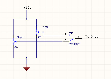
The actual resistance vs pot rotation will be very slightly non-linear, (I doubt you would notice it) because, it's effectively a 10k linear pot with 10k shunt, but the vfd only cares about voltage, and is a high impedance input...so you just pick off the 0-10v from either pot. If you wanted to print a label for speed vs pot rotation, then just note the drive frequency at different positions.
Regards
Ray
-
4th January 2011, 05:06 PM #9
GOLD MEMBER
- Join Date
- Jul 2010
- Location
- Melbourne
- Posts
- 7,775
OK I have a new plan, dew to the limit of 8 pins I will have to make the speed pot separate and moveable between machines or use more din plugs(I have 6 female and 9 male coming so that wont be a problem). Unless I get a new machine/motor(the idea of putting a 3 phase motor on my lathe so I get the smoothness of 3 phase and the bonus of a VSD is starting to take root in my mind) the speed control will likely spend all its time on the mill. Both the shaper and drill will have the speed limited to 50Hz max. Both motors are much older than me and it would be unfair to over speed them in their retirement.

But I would still like to understand you circuit Ray. You're saying the the drive measures the V between ground and the wiper pin of the pot? lol sometimes I can be amazingly thick. I was thinking "but it will flow twice the current, that cant be good" nvm I see what you mean now. Thank you.
The new plan looks like this(for the minute at least lol)
By bringing the machine control V into the switch the machine can't be on when the inverter is switched to it and the speed override from one machine can't override the other machine.
I'll leave the rewiring until I get all the plugs.
Stuart
-
5th January 2011, 11:37 PM #10
GOLD MEMBER
- Join Date
- Jul 2010
- Location
- Melbourne
- Posts
- 7,775
Well while I wait for the for the postie I mounted the box on the mill.
Used the V part of the VSD for the first time to drill the holes in the bracket. I'd always thought "how hard is it to change gears?" lol Sure is harder than turning a pot.
Need to pick up some ferrules for the rewire.
-
6th January 2011, 12:43 AM #11Dave J Guest
You don't have to rub it in to us blokes that have to change belts not gears, lol Originally Posted by Stustoys
I like the way you mounted it off the back of the ram and how neat the wiring is, It looks professional.
As for helping you out with how to wire it up
Where do you pick up the terminals clipped to the rail? Or are they off the mills original elec box?
Dave
-
6th January 2011, 01:20 AM #12
GOLD MEMBER
- Join Date
- Jul 2010
- Location
- Melbourne
- Posts
- 7,775
lol Dave I have belts, I've only used the V pot like five times...... you don't know what you're missing!!!!! Even when I was wiring the pot up I was thinking "this is a waste of time, I'll never use it". I'd drilled a 5mm hole and was opening it out to 10mm. Started the mill and thought thats a little fast, turned the inverter to 40Hz. Converted! As I said in another post I'm already thinking of adding it to my lathe. Sorry to rub it in.

I'm pretty sure I'm on the last version of the wiring now, but it will be a week or so before the din plugs get here and I'm trying to find some ferrules/terminals to suit, so I'll leave it as is until then.
The box and everything in it except the grommet at the back left and the cat5 cable at the front came from some surplus industrial equipment. Even the rubber isolation mounts. The socket and plug aren't in the box they came from ebay.
Stuart
-
6th January 2011, 08:44 AM #13
GOLD MEMBER
- Join Date
- Jul 2006
- Location
- Adelaide
- Posts
- 2,680
Dave
All electrical wholesalers would have 'din rail' terminals...some may not keep it on the shelf, but could get it in.....shop the prices around tho
-
6th January 2011, 01:50 PM #14Dave J Guest
Thanks Eskimo, Have you had a look at the ones on our type of machines? Mine where splitting apart from having 2 and 3 wires leading into them. They just seemed to be the usual Chinese crap, are the ones bought over here better or just the same?
Dave
-
6th January 2011, 02:13 PM #15
GOLD MEMBER
- Join Date
- Jul 2006
- Location
- Adelaide
- Posts
- 2,680
you can still get the chinese crap here Originally Posted by Dave J
but having said that they dont like having too many wires pushed in..they need to be correct size for amount of wires or else parallel them
How many you after..what size ..I have a few box's of them floating around....which I found after I bought the switchboard and dinrail terminals for fitting the VSD to the mill...so now I have lots n lots


Similar Threads
-
WC2000 enclosure pics
By ozhunter in forum DUST EXTRACTIONReplies: 5Last Post: 19th December 2009, 10:34 AM -
Waldo's Dusty Enclosure
By Waldo in forum METALWORK FORUMReplies: 34Last Post: 26th November 2008, 10:49 PM -
Help needed to construct a projector enclosure
By De_Cruelz in forum WOODWORK - GENERALReplies: 19Last Post: 26th June 2005, 02:12 AM
