

 Thanks: 0
 Likes: 0
 Needs Pictures: 0
 Picture(s) thanks: 0
Results 16 to 28 of 28
Thread: Wiring of a single phase motor.
-
26th October 2010, 04:38 PM #16
 Moderate Moderater


- Join Date
- Feb 2006
- Location
- Lindfield N.S.W.
- Age
- 62
- Posts
- 5,643
 BTDT (been there done that) - the point is that in my experience (and I suspect that of many others), such people, who one would assume would be well qualified to advise, are less competent than the average 6 year old
 Originally Posted by Phil Spencer


Electrickery is not that hard and it should be possible to find people who have trade certificates to do the job - the grim reality is that the certificates are meaningless and a sensible person who can read a basic manual would do a better and safer job than the 'qualified' electricians.
That said, the lawyer in me says that you should get the person who has the certificate to do the job and then sue the #### out of him when the motor blows up Cheers
Jeremy
If it were done when 'tis done, then 'twere well it were done quickly
-
26th October 2010 04:38 PM # ADSGoogle Adsense Advertisement
- Join Date
- Always
- Location
- Advertising world
- Age
- 2010
- Posts
- Many
-
26th October 2010, 09:37 PM #17
Senior Member
- Join Date
- Apr 2009
- Location
- Ballina N.S.W.
- Posts
- 371
RayG &eskimo,
Thanks you both for your suggestions, Ray G thanks for the links to the wiring diagrams, the motor does have a double capacitors on it they are just visible in the top left and top right side of photo 449 they have been mostly cut out by the shrinking of the photos.eskimo your experience with electricians sounds similar to mine, when I brought my AL1000D lathe I contacted on seperate occasions two local electricians to wire it up and put a 240 volt power point on the side of the cabinet, when they arrived neither of them after looking in the cabinet knew how to do it, one even had the hide to try and charge me a call out fee. I did find one who knew what he was about and that is who I have called to check out this motors wiring.
Bob
-
26th October 2010, 09:45 PM #18
Pink 10EE owner
- Join Date
- Aug 2008
- Location
- near Rockhampton
- Posts
- 4,304
Pretty scary stuff... Originally Posted by krisfarm
I found installation of a low voltage light onto my AL1000C to be very basic.. I just wired in one of those 240-12V transformers that come with the downlight kit and went from there...
-
27th October 2010, 01:33 AM #19
GOLD MEMBER
- Join Date
- Jun 2008
- Location
- Victoria, Australia
- Age
- 74
- Posts
- 6,132
Hi Krisfarm,
Ok on getting an electrician to wire it up, that's probably the best bet if you aren't sure what you are doing. I've been doing industrial controls for 30+ years and work with electricians all the time, most are pretty good, but, like all trades you do sometimes get the dud's, like the ones that can't follow a circuit diagram, but they are thankfully few. I did have one, otherwise good electrician, last week in WA who didn't know what an oscilloscope was?
The local tafe college here runs courses for those who want to get qualifications to do their own electrical work. The main focus is on safety and regulations. If you are like me and prefer to do things yourself, (that way I know it's done properly) I recommend finding out what courses are available locally.
Whether you do it yourself or not, always get someone qualified to check your work, in the case of high current motor stuff, get someone to do an IR temp check on all your connections after the system has been running under load for a while, you would be surprised how hot an improperly torqued connection can get.
How about some pictures of your belt grinder..
Regards
Ray
-
27th October 2010, 09:39 AM #20
FIG Woodworks, Gentleman Woodworker
- Join Date
- Feb 2005
- Location
- 37 Deg, 52. 697' South 145 deg, 15.627' East. Elevation 78M
- Age
- 71
- Posts
- 1,410
I have been looking at my old records (I use to work for Brook Crompton Betts) going by the part number you have a compressor motor, which was built to handle the short duty cycles required by compressors charging up. These motors were built in what they call a B56 frame and the Kw out put is right at the edge of the frames ability to handle the heat that would be generated, this would be OK for intermitent duty where the motor is at rest while waiting for the compressor tank to discharge before recharging.
You want to use the motor on a grinder so there is a probability that the motor will run for longer periods so, considering the high Kw output in a relatively small frame you may have problems with the motor overheating.
You should proceed carefully if you use this motor, believe it or not those B56 motors were built for special applications and what may look like a normal motor may not be, so you should have the motor checked by an expert, and, not try and do it your self.
I do have the connection diagrams, but going on the way you framed your question it is obvious that you do not have the knowledge, so it would be irresponsible of me to pass me information on.
See my earlier advice about having the motor checked.Two things are infinite: the universe and human stupidity; and I´m not so sure about the universe.
-
27th October 2010, 10:02 AM #21
SENIOR MEMBER
- Join Date
- Mar 2010
- Location
- Nth Qld
- Posts
- 715
I'm a big fan of those motors that have "Brooks" in the name somewhere. That open frame type will eventually suck enough dust and die although in my experience: a mate's disc sander died after 15 years of sucking sawdust and aluminium dust from a combination of wood and from fettling castings to the point where when a capacitor died, the sawdust inside the motor caught fire.
Brooks Crompton Parkinson apparently made only three basic motor frames years ago for economy of production. According to the story I heard from a tech rep, the 1 to 3 HP cap start/run motors all used the same frame and windings. This meant you could change the overload breaker on a 1Hp motor to make it into a 2 or a 3 Hp motor as that was the only difference between them. This ended some time in the 1990's with rising copper costs.
I got to the point where I could replace a shorted section of motor winding or fabricate a new centrifugal switch assembly from scratch using FR4 fibreglass to replace the charred old phenolic resin original to get a good motor running.
Like most skilled occupations you do get a wide variation in electricians from those who are passionate about the job to those who wait for beer o'clock. I gave up on getting electricians to do anything past the most basic of wiring jobs, that said I know some better electricians who got right into the instrumentation/process control side of things and went on to get an electrical engineer's degree. Currently their rules and regulations are written by bureaucrats with pretensions of being lawyers and the trade is poorer for it, there is no real teaching of electrical laws.
Right now my main project is the complete rewire and new electronics, of a 60 year old Blohm surface grinder including rewind of one of the three phase motors after an electrician was allowed near the control box with a screwdriver .
.
-
27th October 2010, 12:18 PM #22
Senior Member
- Join Date
- Apr 2009
- Location
- Ballina N.S.W.
- Posts
- 371
.RC,RayG & Phil Spencer,
Thanks for your posts and advise.RC That was a handy the way you wired your lathe, in my case I had one of those magnetic base/transformer lights so I needed a 240 volt outlet.Ray G & Phil I have included a couple of photos of the grinding station that I am building as you can see it is a work in progress.The belt grinder is based on the KMG style with three different work bars to cover a good variety of jobs I do not like having my bench grinder in close proximity to my lathe and mill hence the need for a mobile grinding station. I intend placing the 8 inch bench grinder on the trolley as well.This machine will only be used for home use not -light duty.When my electrician has a look at the motor, I am sure he will have no problems with it as he does a lot of industrial work. If he has any doubts I can take it to a motor re winder but it is a 70klm trip.
Regards Bob
-
27th October 2010, 03:54 PM #23
FIG Woodworks, Gentleman Woodworker
- Join Date
- Feb 2005
- Location
- 37 Deg, 52. 697' South 145 deg, 15.627' East. Elevation 78M
- Age
- 71
- Posts
- 1,410
Your motor already has a lead on it so why do you need to muck around inside the motor? I would suggest you have your electrician fit a starter.
Two things are infinite: the universe and human stupidity; and I´m not so sure about the universe.
-
27th October 2010, 05:51 PM #24
GOLD MEMBER
- Join Date
- Jun 2008
- Location
- Victoria, Australia
- Age
- 74
- Posts
- 6,132
Hi Krisfarm,
Thanks for the pictures of the belt grinder, looks nicely thought out, and pretty solid. I like the idea of having it mobile, keeping all the grit and sawdust outside.
I've been looking at some of the knife making style grinders on and off, but, seeing yours makes me think it would be a good project for the future. Another one on the long list...
Regards
Ray
PS Your layout looks very similar to the Bader style, which is one I remember looking at.
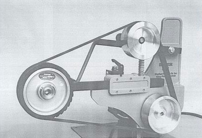
That image is from http://www.pointgallery.com/sharpen/pages/slackbelt.htm
-
27th October 2010, 07:46 PM #25
SENIOR MEMBER
- Join Date
- Mar 2010
- Location
- Nth Qld
- Posts
- 715
It looks like a good solid machine, based on the size of your sanding disc, you may have problems blowing the overload on start up due to the inertia of the steel disc. I have seen a newer style TEFC Brooks 3HP motor cap start/cap run motor have problems with an aluminium disc of 300mm diameter until a higher current overload was fitted. Maybe a TRIAC single phase speed controller would allow a low rpm startup?. Originally Posted by krisfarm
-
27th October 2010, 08:56 PM #26
Senior Member
- Join Date
- Apr 2009
- Location
- Ballina N.S.W.
- Posts
- 371
Phil Spencer
The lead that is connected is what I did just to give everyone something to look at and tell me how to change it.The motor did not have a lead on it.I never intended to run it as wired. Your wording "muck around inside the motor" has me stumped as I have not said or indicated that I ever would do this.
Ray G
The Bader and the KMG grinders are very similar in design, I chose the KMG as the range of attachments looked more suitable for my use.
Graziano.
The disc is 14" diameter and is made of cast aluminium, thanks for your advise on the starting load I will bring it up with the electrical experts when I talk to them.
Thanks to all for your help I have learnt a lot from everyone and have deceided to make the trip and take the motor in to a re winder tomorrow. I will advise there results.
Bob
-
28th October 2010, 08:34 AM #27
GOLD MEMBER
- Join Date
- Jul 2006
- Location
- Adelaide
- Posts
- 2,680
mmm?...maybe a magnetic clutch could be an answer if your motor cant get away.....making the belt slip on start up is another option.....but that wears out pulleys ...(and belts but they are cheap) Originally Posted by krisfarm
-
28th October 2010, 08:10 PM #28
Senior Member
- Join Date
- Apr 2009
- Location
- Ballina N.S.W.
- Posts
- 371
eskimo.
Thanks for the suggestion but I do not think it will be needed as I have been using this disc for just on 40 years driven by a 1/3 hp motor that I rescued from a discarded washing machine, it did help it to give it a bit of a push start.
For all other posters.
I took my motor into an electric motor re winder and he gave it the once over, the results were that I had the motor wired correctly ( see original photo) and that it would do the job that I intended it for. I asked about the open frame construction with dust and heat issues. He suggested that I just blow it out every now again with an air nozzle. He also said he has seen lots of these motors over the years and they give good service. When I reinstalled it I tried it out it started both the face plate and drum grinder together instantly.Now to get on and finish the rest of the project.
Regards Bob


Similar Threads
-
Single Phase Motor Question
By Glenhuon in forum METALWORK FORUMReplies: 3Last Post: 22nd October 2009, 10:49 AM -
replacing three phase motor with single phase
By rev in forum HAND TOOLS - POWEREDReplies: 18Last Post: 16th December 2007, 04:32 PM -
Capacitors for single phase motor
By boban in forum HAND TOOLS - POWEREDReplies: 21Last Post: 2nd June 2005, 05:45 PM
