

 Thanks: 0
 Likes: 0
 Needs Pictures: 0
 Picture(s) thanks: 0
Results 91 to 105 of 159
Thread: Wow - huge price difference
-
1st September 2012, 09:22 PM #91
 SENIOR MEMBER


- Join Date
- Sep 2011
- Location
- Ballarat
- Age
- 65
- Posts
- 2,659

My head just exploded.
Phil
-
1st September 2012 09:22 PM # ADSGoogle Adsense Advertisement
- Join Date
- Always
- Location
- Advertising world
- Age
- 2010
- Posts
- Many
-
1st September 2012, 09:34 PM #92
GOLD MEMBER

- Join Date
- Aug 2011
- Location
- Melbourne
- Posts
- 2,951
Hey, on a brighter note, I have just been looking through my collection of MEW and I found an article on EXACTLY what some of you are doing here. It's in FEB 2009 issue page 16 "Low-Cost High performance Digital Rev-Counter". Rob, the article uses what seems to be the same tacho module and the guy makes a 60 tooth optical disc to incorporate the use of the same optical sensor. He also gives the circuit diagram to interface the output to the tacho module and makes his own 5V supply to drive it. Pretty much exactly as we have been discussing but it all there on paper for you to read and get your head around.
Hope this helps.
Cheers,
Simon
-
1st September 2012, 09:53 PM #93
Blacksmith, Cabinetmaker, Machinist, Messmaker
- Join Date
- Dec 2011
- Location
- Canberra
- Age
- 40
- Posts
- 4,467
Interesting circuit Simon.
Not the way i would do it, with the use of a pre amp pull up resistor and post amp pull down resister, but i'm sure it works!
Exploding heads is just one of the services provided at the house of confuselectrics!
Its ok Phil, we know what we are doing ......honest.....
1915 17"x50" LeBlond heavy duty Lathe, 24" Queen city shaper, 1970's G Vernier FV.3.TO Universal Mill, 1958 Blohm HFS 6 surface grinder, 1942 Rivett 715 Lathe, 14"x40" Antrac Lathe, Startrite H225 Bandsaw, 1949 Hercus Camelback Drill press, 1947 Holbrook C10 Lathe.
......honest.....
1915 17"x50" LeBlond heavy duty Lathe, 24" Queen city shaper, 1970's G Vernier FV.3.TO Universal Mill, 1958 Blohm HFS 6 surface grinder, 1942 Rivett 715 Lathe, 14"x40" Antrac Lathe, Startrite H225 Bandsaw, 1949 Hercus Camelback Drill press, 1947 Holbrook C10 Lathe.
-
1st September 2012, 10:22 PM #94
SENIOR MEMBER
- Join Date
- Jun 2012
- Location
- SA
- Posts
- 1,478
Thanks Simon.
The only electronic circuit I ever built was a crystal set about 50 years ago.
And one of those graphic equaliser kits where you solder part A into holes A1 and A2.
They both worked - but it was a minor miracle of sorts.
Had a reasonable afternoon with my aluminum (as the yanks would say) heat sink. Found a place to put it and after much hunting around found an enclosure for the DC drive unit, two fuses, and power switch - an old XT power supply case - which is being suitably modified/resized with a disc cutter in my $20 air die grinder. Damn those things are good for small light stuff.
Here's a photo of the motor cradle and the half completed DC drive cover and heat sink.
You can see the section of power supply case I sliced off in the background, and also the piece I cut out of the base so that the DC drive controller can bolt directly to the heatsink - with a smear of thermal compound between the two.
Am quite pleased with the result so far.
The cradle still has to have four holes drilled and tapped into the end plate.
The heatsink is actually upside down in the photo. I will probably take another 5 mm off the XT case to move it back flush with the edge of the heatsink, if the DC drive will allow it. The control sits back from the front vent slots by about 5 mm to allow air flow through the case.
I'm using a 90 V KBI -240DS drive as a template until my 180 v drives arrive. Same chassis.
Rob
-
1st September 2012, 11:00 PM #95
GOLD MEMBER
- Join Date
- Aug 2010
- Location
- Bendigo
- Age
- 72
- Posts
- 1,986
Simon, would you mind publishing (or e-mailing me) the rest of the tacho article?
I've read what is there and would like to know more.
I've ordered one of the frequency counters a few days ago and would like to build a rev counter for my lathe too. I have a few infrared optical sensors out of a dismantled printer in my 'useful' box.... By the way, do these LED unit divide by 60 internally? It would be good to read rpm instead of rps or we need a 60 hole disk....
Edit: oops - just re-read the specs: you can set the mode and even custom dividers..... so any number of holes in the disk are possible.
This looks simple enough.
Cheers,
Joe
-
2nd September 2012, 12:58 AM #96
Senior Member
- Join Date
- Apr 2010
- Location
- ringwood vic
- Posts
- 251
Hey Fellas ,
As Rob says lets forget the DC motors, just connect the lathe to the treadmill with a flat belt and run like buggery.
See Yuz,
Martin
-
2nd September 2012, 08:03 AM #97
GOLD MEMBER
- Join Date
- Aug 2011
- Location
- Melbourne
- Posts
- 2,951
Hey thats it! You may laugh at me now but when power bills get so high that we can't afford to switch on our machines, I will be able to go for a run and do a project! Originally Posted by toolman49


Simon
-
5th September 2012, 02:20 PM #98
SENIOR MEMBER
- Join Date
- Jun 2012
- Location
- SA
- Posts
- 1,478
Simon,
I saw these two Hall sensor circuits on Ebay - cheap.
Would either of these make it easy to connect up the tacho ?
New Hall Switch Sensor Module Smart Car Accessories JS1826 | eBay
Hall Sensor Module M44 Switch for Magnetic Field Detecting 16mA DC 0-15V | eBay
Rob
-
5th September 2012, 05:24 PM #99
Blacksmith, Cabinetmaker, Machinist, Messmaker
- Join Date
- Dec 2011
- Location
- Canberra
- Age
- 40
- Posts
- 4,467
Either looks like it should work Rob.
My tacho and he sensors turned up today. Just a shame I'm 600kms away......1915 17"x50" LeBlond heavy duty Lathe, 24" Queen city shaper, 1970's G Vernier FV.3.TO Universal Mill, 1958 Blohm HFS 6 surface grinder, 1942 Rivett 715 Lathe, 14"x40" Antrac Lathe, Startrite H225 Bandsaw, 1949 Hercus Camelback Drill press, 1947 Holbrook C10 Lathe.
-
5th September 2012, 09:16 PM #100
GOLD MEMBER
- Join Date
- Aug 2011
- Location
- Melbourne
- Posts
- 2,951
As Ewan said. Either will work. Personally I'm not too familiar with the setup. Not sure how close the magnet would need to come for it to register a pulse. It would certainly be a more reliable setup than an optical sensor if used in an oily environment such as inside the gearbox of a mill/drill. Originally Posted by nearnexus
Simon
-
5th September 2012, 09:47 PM #101
SENIOR MEMBER
- Join Date
- Jun 2012
- Location
- SA
- Posts
- 1,478
Both units are certainly not big bucks.
I like the look of this one as it has a stabilised output option.
Hall Sensor Module M44 Switch for Magnetic Field Detecting 16mA DC 0-15V | eBay
So I might go that way. i've sent off the specs to an electronics guru I know to see what he recons.
I'm pretty hopeless on this stuff, so be interesting to see what he recommends.
Cheers
Rob
-
5th September 2012, 10:51 PM #102
Blacksmith, Cabinetmaker, Machinist, Messmaker
- Join Date
- Dec 2011
- Location
- Canberra
- Age
- 40
- Posts
- 4,467
A 15c he sensor in its own might do the job yet. The good thing about a tiny sensor is ease of fitting and you can easily seal it in heatshrink and epoxy to keep the oil out. Just as easy to hook up too if it works with no other components. Also plenty easy to replace if needed.
1915 17"x50" LeBlond heavy duty Lathe, 24" Queen city shaper, 1970's G Vernier FV.3.TO Universal Mill, 1958 Blohm HFS 6 surface grinder, 1942 Rivett 715 Lathe, 14"x40" Antrac Lathe, Startrite H225 Bandsaw, 1949 Hercus Camelback Drill press, 1947 Holbrook C10 Lathe.
-
7th September 2012, 01:57 PM #103
SENIOR MEMBER
- Join Date
- Jun 2012
- Location
- SA
- Posts
- 1,478
Hi Ewan,
I've found the pinouts for the optical sensor, so I'm going to give it a go. They are as you or Simon suggested.
The tacho can't be far away.
I've spent the morning machining up a mounting plate for the end of the spindle pulley and it's working out well - made it out of the alloy disc from a scrap lapidary machine I found on junk day.
Yes, nothing better than walking the dog on junk day. Pity they've done away with mass collections in our area - it was a real bonanza. Amazing what people throw out.
I actually picked up a complete bandsaw in bits, which I've been using for the last 10 years. And then there's the workshop vacuum cleaner, lots of electric motors, and the weed sprayer etc. etc - but I digress.
The optical sensor looks to probably have a minimum 5 volt requirement, and I'm hoping it has a current limiting function as it will have to share the VCC voltage from a 9 v plugpack.
Anyway, nothing to lose.
If it craps out I'l just move on to a Hall sensor
If you see smoke on the horizon it will probably be me.
Rob
-
12th September 2012, 09:11 PM #104
Blacksmith, Cabinetmaker, Machinist, Messmaker
- Join Date
- Dec 2011
- Location
- Canberra
- Age
- 40
- Posts
- 4,467
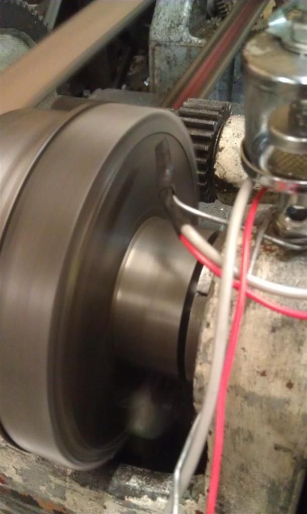
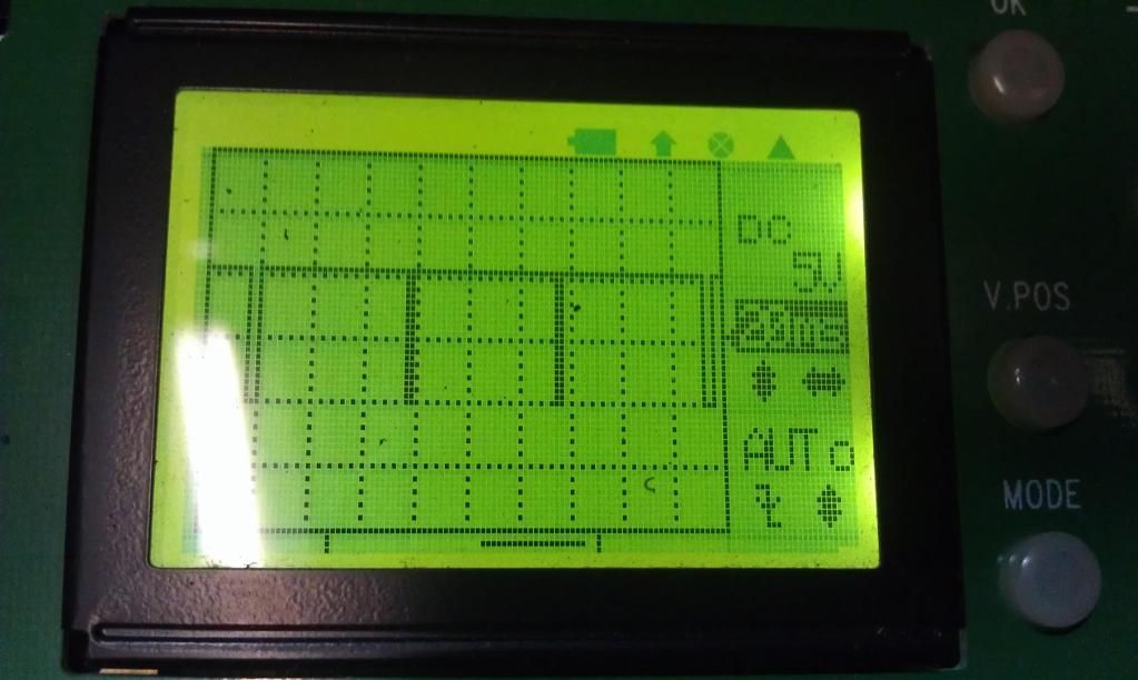
I had a play with the HE sensors today. I was misled when i was away and the tacho has still not arrived. I tried to use the gear teeth with a magnet on the outside of the sensor, but my magnets are to strong and the distances between the magnet, sensor and gear have to be spot on. I actually ground one sensor half away rubbing it on the gear....

Any way, i ended up with just a small magnet on the side of the bull gear and a high tech holder (made from fencing wire heat shrunk onto the sensor ) and i get a good strong signal even at 10mm from the magnet. The sensors i use are inverse to how i thought they would be, they switch low when they magnetic flux goes high, so i used a 10k (or was it 100k?) pull up resister and voila, nice square 12v lows.
 1915 17"x50" LeBlond heavy duty Lathe, 24" Queen city shaper, 1970's G Vernier FV.3.TO Universal Mill, 1958 Blohm HFS 6 surface grinder, 1942 Rivett 715 Lathe, 14"x40" Antrac Lathe, Startrite H225 Bandsaw, 1949 Hercus Camelback Drill press, 1947 Holbrook C10 Lathe.
-
12th September 2012, 09:25 PM #105
GOLD MEMBER
- Join Date
- Nov 2007
- Location
- melbourne australia
- Posts
- 2,643
My tacho turned up yesterday. I'm off on holiday, so get cracking on the design you blokes!


Similar Threads
-
meter cube price to board size price - conversion tool
By old_picker in forum TIMBERReplies: 7Last Post: 27th January 2013, 09:21 PM -
What to do with a huge burl
By Microbe in forum WOODWORK - GENERALReplies: 51Last Post: 29th June 2008, 10:57 AM -
Huge Redgum log
By DJs Timber in forum SMALL TIMBER MILLINGReplies: 23Last Post: 3rd September 2007, 03:36 PM
