

 Thanks: 0
 Likes: 0
 Needs Pictures: 0
 Picture(s) thanks: 0
Results 16 to 23 of 23
Thread: Weird Roof Plan
-
26th February 2007, 02:37 AM #16
 Novice


- Join Date
- Feb 2007
- Location
- Melbourne, Victoria
- Posts
- 21
 Precicely my thought. Cabletrusses are Ugg err leee tho. If it's too small, double it ;-)
 Originally Posted by pawnhead

I built a small railgun, just to see if I could make the principle work. It worked, but it didnt punch holes in the physics lab wall like I hoped it would Originally Posted by pawnhead
 It barely dented paper.
So do I. I just wondered if your geek friends could prove it ;-) Originally Posted by pawnhead
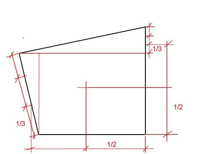
Your diagram is exactly the right way to start with subdividing the shape. But you need the centroids of those two triangles (you're nearly there, you've got the thirds marked out on the top one) and the centroid of the rectangle (which obviously isn't what you've marked, but is easy). Then you need the areas of each of those shapes, and you have to find the weighted average of the three centroids you've marked. The weightings are the respective areas.
So, talking about your diagram as being 'x' across the page and 'y' up and down the page, you do this:
Call the bottom right 'zero'.
Get the x distance (measuring left) to the centroid of the square, and multiply it by the area of the square. This is x1.
Get the x distance to the centroid of the top triangle, and multiply it by the area of that top triangle. This is x2
Get the x distance to the centroid of the left triangle, and multiply it by the area of that left triangle. This is x3
Add up x1, x2 and x3. Divide this figure by the total area of the shape. This is the x distance of the overall centroid.
Repeat for the 'y' direction.
Job done.
It sounds simple, but you've got to locate the top left corner mathematically. You could either do it with trig, or with a quadratic simultaneous equation (I think!)
I'd still get a piece of cardboard
-
26th February 2007 02:37 AM # ADSGoogle Adsense Advertisement
- Join Date
- Always
- Location
- Advertising world
- Posts
- Many
-
26th February 2007, 10:26 AM #17
SENIOR MEMBER
- Join Date
- Apr 2005
- Location
- Sydney
- Age
- 63
- Posts
- 1,619
You could design your own and it wouldn't have to project beyond the bottom of the beam in the centre. It could run from there to the top of the hips, and return around the corner for bracing. You could cover it all up if you wanted. Originally Posted by ChipperChip
 Ah, so you want them to get into some engineering then? I studied it as a part of the building course that I did. There was no carpentry taught, but for some reason they taught us how to design trusses, slabs, beams, etc, so I have an understanding of how to calculate loads and vectors, but I'm not sure where all my engineering span/load books are. I'd need to refresh my memory that's for sure. Originally Posted by ChipperChip
That sounds like the formula described by Assassinator_2 Originally Posted by ChipperChip
You like your cardboard. Originally Posted by ChipperChip
Ah, now I see!
You got your license from a Corn Flakes box click--->, or a packet of 'Chipper Chips'. 
I'll have a look at them later. Originally Posted by Spaski

Cheers

-
26th February 2007, 03:14 PM #18
GOLD MEMBER
- Join Date
- May 2003
- Location
- Kuranda, paradise, North Qld
- Age
- 62
- Posts
- 5,639
Easy way out?
With all the headaches involved in
1) calculating how and where to pitch the roof, and
2) all the fartasring about building it as it will all be bastard angles,
mightn't it be easier to shift a couple of the polesto at least make it a true rhombus?
Mick"If you need a machine today and don't buy it,
tomorrow you will have paid for it and not have it."
- Henry Ford 1938
-
26th February 2007, 04:11 PM #19
New Member
- Join Date
- Feb 2007
- Location
- Brisbane
- Posts
- 7
Dimensions roughly correct. Roof pitch would be 15 or 20 degrees.
Cheers,
Brad
-
26th February 2007, 07:09 PM #20
Novice
- Join Date
- Feb 2007
- Location
- Melbourne, Victoria
- Posts
- 21
Only problem with that is you'd then be introducing an offset compressive load and the beams would tend to bow out. You'd need to double the beam to hide your cabletruss inside it, by which point you wouldnt need the cabletruss Originally Posted by pawnhead
Bah. One big beam and be done with it
I wanna do that course! Where did you do it? Originally Posted by pawnhead
It is exactly that forumula - I just wrote it out as a longhand stepwise process for the less mathematically minded around here to try to get their heads around it. Me, for instance ;-) Originally Posted by pawnhead
Uh huh Originally Posted by pawnhead
 It's such a neat trick.
Close. It was a UK Corn Flakes box ;-) My licence has a different chicken on it Originally Posted by pawnhead
Given those dimensions, this is where your centroid is. All dims are in plan view, not actual beam lengths - I haven't figured out the pitched dimension for you. That's easy to do from the numbers you have here. Decide which face you want to be your known pitch, calculate the peak height (using trig), and use that to decide the pitch of the other three faces (trig again) and the beam lengths for your hip rafters using pythagoras's theorem. Originally Posted by Spaski
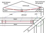
I've included angles on one drawing to make your mitres on your perimeter beams easy If you're using a (big!) compound mitre saw you will be able to do your plumb cuts (from your beam pitches - trig) and bevels (from this drawing) at the top easily and neatly too. Sorry about all the extra circles on that drawing - my free DWG renderer is... well, it's free. Oh, and yes there are some rounding errors.
The last drawing is just to show you what happens if you simply split the angles at the corners in half. The beams dont come together - but they do cluster neatly around the centroid. Pawnhead, I wonder if the centroid of that irregular polygon at the middle might be a better peak location.. hmm... Somebody stop me.
The zip file contains the spreadsheet if anyone wants to check my calculations. I pulled all the dims out of my CAD tool as you can see, rather than trying to locate the corners with trig - and then just pumped it into the spreadsheet. Btw, brad, your measurements are very good. Having set up the shape using one diagonal, my CAD differs from your other diagonal by 0.33mm
-
26th February 2007, 09:20 PM #21
SENIOR MEMBER
- Join Date
- Apr 2005
- Location
- Sydney
- Age
- 63
- Posts
- 1,619
He's stuck with what he's got I'd say. It would be a headache to move them now. Originally Posted by journeyman Mick
Just use a pair of 190X45s. One on the outside, and one on the inside of the poles, with spacers bolted through @ 1200 C/S. Use some Booker Bar in between for the cabletruss on the long spans. They won't deflect out because the hips support each other remember. Originally Posted by ChipperChip
Well twenty years ago they called it the "Builder's Certificate Course" when I studied at Sydney TAFE. I used to ride my push bike there three nights a week, and one time I hopped of my bike on the Harbour Bridge (if I was using the cycleway, instead of holding on to a truck, or car roof rack and getting a tow over the bridge) , climbed up over the barbed wire, across the road, and up to the top. Originally Posted by ChipperChip
 . I didn't have to pay as you do today. . There was lots of graffiti up there then.
They changed it to a Diploma whilst I was midway through the course, the bums. I can't add "Dip. Bldg." to my name. I don't know if they still offer it, but shortly after I did mine, I lent all my assignments to a mate doing the course after me, and he got higher marks by just copying my work.
They taught you enough to calculate all the loads and vectors of the Harbour Bridge if you wanted. The vast majority of its design strength goes to supporting its own weight.
That's a handy tool you've got there. That's everything he'll need apart from the hip lengths and pitches. Easy enough to work out from there. He just has to decide the pitch since they will all be different to each other. Originally Posted by ChipperChip
Cheers
-
27th February 2007, 12:16 AM #22
Novice
- Join Date
- Feb 2007
- Location
- Melbourne, Victoria
- Posts
- 21
Originally Posted by pawnhead
But we ARE talking about trussing the perimeter beams, right? My only thought was that if you put a cabletruss down one side of a beam, the beam will bow away from the truss. how much clearance are you suggesting between these beams? If you put them one each side of the pole you get quite a big gap. Is your standard Booker going to be able to take the side load of a cable truss tied in between those beams with threaded rod only holding 90mm of bending moment.
Can you do a quick sketch? I'm interesting in what you've got in mind in more detail..
Btw, the cad I'm using is a free A9CAD from A9, and the DWG renderer is "Free DWG viewer'
My apologies if this is a bit scrambled. I'm excrutiatingly tired.
-
27th February 2007, 09:06 AM #23
SENIOR MEMBER
- Join Date
- Apr 2005
- Location
- Sydney
- Age
- 63
- Posts
- 1,619
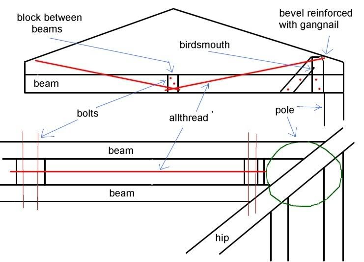
A Cable Truss has two cables. One on each side of the beam. I was just throwing the idea of making your own out of booker bar into the pot, but I hadnt really thought about it, however after a bit of pondering I came up with this : - Originally Posted by ChipperChip
If you used a double 190X45 set up, then this could be retro fitted after if they sagged. It could be fitted to the long spans only. It would probably be cheaper than buying something that spans over four metres, and it would allow you to have a beam of minimal depth. It wouldnt look too obtrusive either.
The principle is a bit like a mast spreader on a yacht.
Of course all of the loads should be calculated, but I reckon 190X45 with a 12mm allthread would do the job. Theres a bit of work involved in it though. Youre constructing your own truss on site.
Cheers click--->


Similar Threads
-
The Plan
By trevorZ in forum WOODIES JOKESReplies: 1Last Post: 31st May 2003, 09:00 AM
