

 Thanks: 0
 Likes:
  Needs Pictures: 0
 Picture(s) thanks: 0
Results 181 to 195 of 308
Thread: Mars Lathe DC motor conversion.
-
23rd November 2012, 03:31 PM #181
 GOLD MEMBER


- Join Date
- Jul 2010
- Location
- Melbourne
- Posts
- 7,775

Well one of the inductive sensors turned up today. Seems there is a hole in my plan.
This one seems to only be good for about 800rpm 27Hz. Now I might be able to get a little more its a long way short of 500Hz. Its just dawned on me that that spec is likely tested with a 1/2 on 1/2 off setup. When set up on the dogs its more like 1 on 5.75 off.
Lucky I have a Hall effect sensor on the way as well
Stuart
-
23rd November 2012 03:31 PM # ADSGoogle Adsense Advertisement
- Join Date
- Always
- Location
- Advertising world
- Posts
- Many
-
23rd November 2012, 06:36 PM #182
GOLD MEMBER

- Join Date
- Aug 2011
- Location
- Melbourne
- Posts
- 2,951
Hi Stuart,
I just got my induction sensor too. What makes you think it's only good to 27Hz? Did you get specs with yours? The basic wiring diagram at the base of my actual sensor is ALL in Chinese, I had to guess which is +, GND and output! It works OK though, even on aluminium, I don't know why but I had it in my head that it only works with magnetic materials but I think that is for Hall effect sensor, I got that many sensors now that I confusing myself!
If my induction sensor is only good to 27Hz then that's my plan up in smoke too! Well, once I get past 1600 rpm anyway! 27Hz, that's crap, who makes a sensor rated to only 27Hz?!!!! No wonder they are cheap.
The 1 on 1 off or 1 on 5.75 off I would thought would not be an issue since I'm assuming it's edge triggered?
Simon
-
23rd November 2012, 06:40 PM #183
GOLD MEMBER
- Join Date
- Aug 2011
- Location
- Melbourne
- Posts
- 2,951
Product Name Inductive Proximity Switch Model LJ12A3-2-Z/BX Theory Inductive Sensor Wire Type 3 Wire Type (Black, Brown, Blue) Switch Appearance Type Cylinder Type, Metal Shell Output Type NPN NO(Normal Open) Diameter of Column Sensor 12mm Detecting Distance 7mm Supply Voltage DC 6-36V Current Output 300mA Response Frequency 0.5kHz Detect Object Iron Total Size 6.6 x 2cm/2.6'' x 0.8'' (L*W) Cable Length 1.1m/43.3'' External Material Plastic, Metal Net Weight 42g Color Silver Tone, Orange, Gray Package Content 1 x Inductive Proximity Switch
According to this mine is OK to 500Hz. Ah! "Detect Object: Iron" That's where I got it from, thought it was the voices in my head!
Soon find out!
Simon
-
23rd November 2012, 07:10 PM #184
GOLD MEMBER
- Join Date
- Jul 2010
- Location
- Melbourne
- Posts
- 7,775
Hi Simon,
I bought one like that and another that looks just the same with only 4mm detecting distance and no Hz spec. Not sure which on turned up, I'll try and work it out.
I might have confused you. I think it only works at 27Hz because of my setup. It works ok at slow speeds but at about 800rpm it stops triggering. I am guessing this is because the dog isnt "there" long enough. Time wise my math says if I went to a single trigger point that covered 180 degrees it would run at 182Hz. So still a little on the low side but the dogs arent the perfect shape and have a slightly different distance from the sensor.
What are you planning to use to trigger yours?
Stuart
-
24th November 2012, 06:36 AM #185
GOLD MEMBER
- Join Date
- Aug 2011
- Location
- Melbourne
- Posts
- 2,951
Hi Stuart,
OK I'm with you now. Originally I was going to make a setup inside the mill head but installing a sensor immersed in oil and routing the cable outside seemed unnecessarily complex. I'm going to mount a pickup on the base of the quill shaft underneath. I plan on making a clamp on disk (about 10mm thick) with two pickup nodes. This will clamp on the quill shaft.
I should have this made and installed on Tuesday (working saturday & Sunday ). I'll post some pics when I get it done.
Cheers,
Simon
-
26th November 2012, 08:31 PM #186
Senior Member
- Join Date
- Sep 2008
- Location
- Riddells Creek
- Posts
- 300
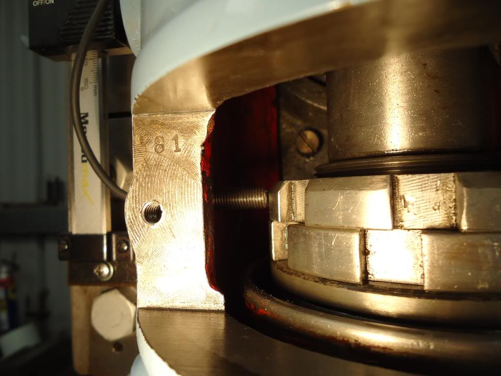
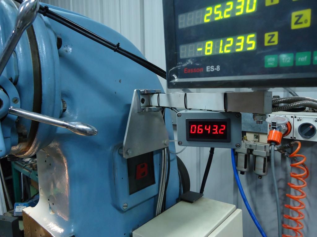
Here's a few pictures of tacho setup on my mill, it has worked very well so far.
I drilled, spotfaced and tapped a hole through the side of the vertical head to allow the inductive sensor to pick up directly on the slots in the bearing locknut.
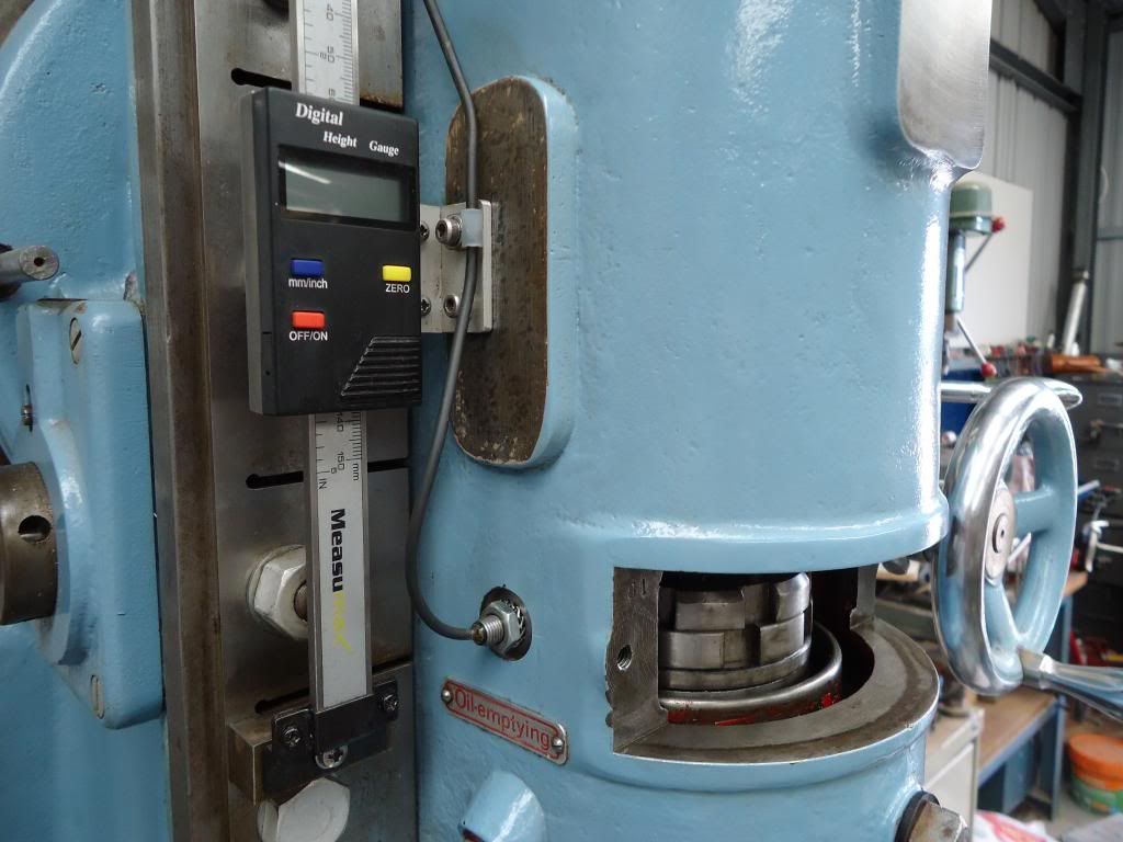
The sensor has an LED potted into the end next to the cable to indicate that it is registering a signal.
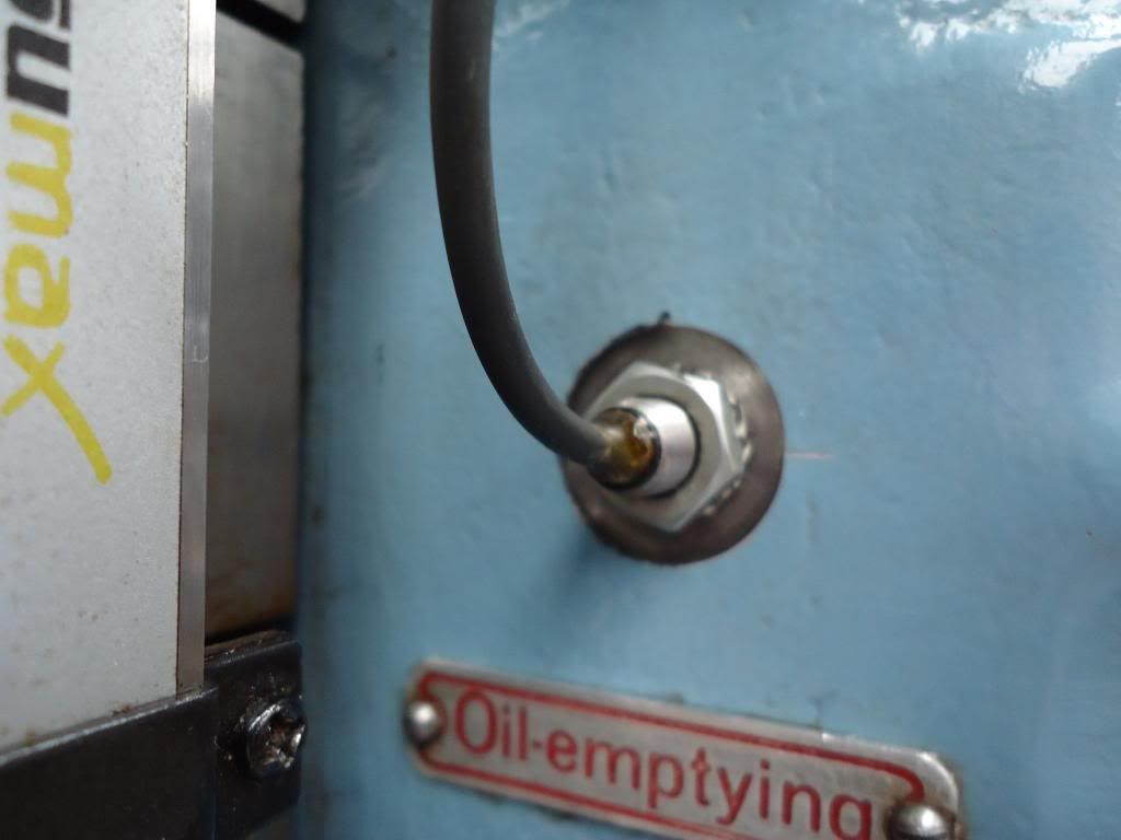
The particular sensor needs to be 1mm away from the rotating surface, this distance is rather critical with this type of sensor but is easily adjusted with a screw in type.
-
26th November 2012, 08:39 PM #187
Philomath in training
- Join Date
- Oct 2011
- Location
- Adelaide
- Age
- 59
- Posts
- 3,149
Techo, we have rules here you know.
Posting pictures like that in a thread about lathes is not on.
Please find the "Show us your mill thread" and post more pics about that mill!
Michael
-
26th November 2012, 08:46 PM #188
Blacksmith, Cabinetmaker, Machinist, Messmaker
- Join Date
- Dec 2011
- Location
- Canberra
- Age
- 40
- Posts
- 4,467
My guess is that its a K&T....puts some pics and info in show us your mill Please!
1915 17"x50" LeBlond heavy duty Lathe, 24" Queen city shaper, 1970's G Vernier FV.3.TO Universal Mill, 1958 Blohm HFS 6 surface grinder, 1942 Rivett 715 Lathe, 14"x40" Antrac Lathe, Startrite H225 Bandsaw, 1949 Hercus Camelback Drill press, 1947 Holbrook C10 Lathe.
-
27th November 2012, 10:13 PM #189
Senior Member
- Join Date
- Sep 2008
- Location
- Riddells Creek
- Posts
- 300
The only "Show Us Your Mill" thread I could find was related to portable timber mills, is there another?
Lex.
-
27th November 2012, 10:27 PM #190
GOLD MEMBER
- Join Date
- Jul 2010
- Location
- Melbourne
- Posts
- 7,775
-
29th November 2012, 02:44 PM #191
GOLD MEMBER
- Join Date
- Jul 2010
- Location
- Melbourne
- Posts
- 7,775
Well I don't know what I've done.
First time I hooked the Hall sensor up I paralleled it with an inductive sensor by mistake.
Both leds on the Hall sensor are on , magnet switches the sensor led off. Tacho worked but only at slow speed.
Rewired without the inductive sensor, now just the power light comes on and I cant get the magnet to switch.
If I disconnect AO from the yellow wire on the tacho, the sensor will then switch but thats not a lot of use lol. Still only at very slow speeds.
The speed maybe fixed with a bigger magnet and a more carefully adjusted sensor.
Have I toasted something?
Any ideas?
Getting close to going back to doing the maths in my head
Stuart
-
29th November 2012, 07:22 PM #192
GOLD MEMBER
- Join Date
- Aug 2011
- Location
- Melbourne
- Posts
- 2,951
Hi Stuart,
You're a smarter man than me so if you can't figure it out, what hope have I got? LOL!
Both my hall switch and induction sensor have an LED in their rear but it only comes on when they detect. My sensors have a Black, Brown and a Blue wire. Their choice of wire colours confuses me but with mine Black is GND (no surprises) Brown is +Vcc and blue is the output signal. I have incorrectly wired BOTH sensors (I powered up their outputs by mistake as I thought the blue wire was +Vcc) and after I figured out my mistake I rewired them and they still work fine. According to the literature, my sensors (yours probably the same) can source 300mA which is a fair amount for a sensor, so they must be fairly robust.
Tomorrow I have been promised 1/2 day in the shed so I plan on tapping the grub screws on my sensor pickup for my mill, I'll do some peed tests to see how responsive the sensor is. I have yet to test my sensors in real situations, only waved the target material near them to check that they go on and off. I may find too that the speed of the signal may get beyond the frequency response of the sensor and that the 500Hz spec is a load of crap! I would expect that an erratic result will occur as it approaches it's limitations.
I'll report back.
Simon
-
29th November 2012, 08:21 PM #193
Blacksmith, Cabinetmaker, Machinist, Messmaker
- Join Date
- Dec 2011
- Location
- Canberra
- Age
- 40
- Posts
- 4,467
Hmmm...sound interesting..... Originally Posted by simonl


Hi Stuart,
Not sure on the sensors you are using, do you have an oscilloscope so you can see what is going on?
Did you want me to put a couple of the HE sensors i am using in the post? They just need a pull up resistor and i have tested them to over 4k. No flashing lights and you will have to mount them on a small PCB and i suggest dipping them in epoxy but they do work!1915 17"x50" LeBlond heavy duty Lathe, 24" Queen city shaper, 1970's G Vernier FV.3.TO Universal Mill, 1958 Blohm HFS 6 surface grinder, 1942 Rivett 715 Lathe, 14"x40" Antrac Lathe, Startrite H225 Bandsaw, 1949 Hercus Camelback Drill press, 1947 Holbrook C10 Lathe.
-
29th November 2012, 10:47 PM #194
GOLD MEMBER
- Join Date
- Jul 2010
- Location
- Melbourne
- Posts
- 7,775
Hi Simon,
Not so sure about that.
"Both my hall switch and induction sensor" you mean a Capacitive and Inductance Sensor? (both mine have LEDS but I am talking about one of these.
Hall Sensor Module M44 Switch for Magnetic Field Detecting 16mA DC 0-15V | eBay
You'll know when you hit the limit, the rpm starts to drop as it misses pulses(of course yours may work just fine with your encoding ring(I think thats the correct name?). If not you can always make a new one with 90derees segments.
Hi Ewan,
I'm using the same sensor and tacho as Rob used here
https://www.woodworkforums.com/f65/ma...ml#post1565977
Thought the tacho is a 12-24V one
0.56" DIGITAL Red LED Frequency and Tachometer Rotate Speed Meter DC 12-24V | eBay
No scope.... though I have been looking at them for the last few months but I hadn't convicted myself I need one.
Pull up resistor. do I need one of them? I read about them in another post. maybe I should reread this thread properly rather than flipping through it.
I'll play with this one a little longer.... its likely me doing something stupid....... If I cant get it going I'll gladly take you up on your offer. I had planned on removing the sensor from the board anyway.
Stuart
-
30th November 2012, 12:17 PM #195
GOLD MEMBER
- Join Date
- Aug 2011
- Location
- Melbourne
- Posts
- 2,951
Hi Stuart, my mistake about the sensor!
Hey, I think we may be in the same boat now. Do you remember me saying that I found the wiring colours a little confusing? Well I think I may have let the magic smoke out of the sensor! After connecting it up and seeing it do nothing, I had a look at an email from the seller after I asked them about wiring. Turns out it's: Brown +Vcc, Blue Gnd and Black is signal. It had been a while since I played with it and forgot that I forgot which wire goes where!
Anyway, to cut a long story short, I wired it up incorrectly and now I can't get it to work. The LED at the rear indicates a signal but the output is fixed at +Vcc. Ahhhhhhh!
I'm about to order another one, not that the $6 worries me, it's the painful 3 week wait!
Stuart, I hope you have beeter luck than me.
BTW, with the LED tacho, the instructions are confusing. S1 is the switch on the LHS (looking at the back with the cover off) and S2 is on the RHS? I have worked out how to select between freq and tacho, I assume you use slection "3" unfiltered? I think I have also managed to select the divider (3 for my situation) but how do you change the decimal point and it's resolution?
Had a look back over the "Wow huge Price Difference" thread but could not find anything.
Cheers,
Simon


Similar Threads
-
Mars bar no, Mars lathe!
By neksmerj in forum METALWORK FORUMReplies: 20Last Post: 29th September 2012, 08:18 PM -
MARS Atlas Lathe restoration
By onthebeachalone in forum METALWORK FORUMReplies: 39Last Post: 18th July 2012, 11:53 PM -
Lathe motor/drive conversion
By bin555 in forum METALWORK FORUMReplies: 34Last Post: 14th June 2012, 08:21 PM -
Adjusting or replacing babbit bearings in a Mars Great Scot lathe (brisbane)
By unixbigot in forum METALWORK FORUMReplies: 52Last Post: 9th August 2011, 11:37 PM -
AL320g Lathe CNC Conversion
By Holycross in forum METALWORK FORUMReplies: 2Last Post: 19th June 2011, 09:30 PM
