

 Thanks:
  Likes:
  Needs Pictures:
  Picture(s) thanks:
Results 121 to 135 of 264
Thread: Yet another Router table build.
-
19th June 2018, 07:10 PM #121
 Woodworking mechanic


- Join Date
- Jan 2014
- Location
- Sydney Upper North Shore
- Posts
- 4,472

How are you powering the measuring head - from the processor board, with an external circuit or does the measuring head unit gave its own power supply?
Is the data similar/same as this?
Chinese Scales
Thats what I’ve been getting out of my vernier and height gauges.
-
19th June 2018 07:10 PM # ADSGoogle Adsense Advertisement
- Join Date
- Always
- Location
- Advertising world
- Posts
- Many
-
19th June 2018, 07:52 PM #122
Supporting my wife's hobby.
- Join Date
- Nov 2013
- Location
- Caboolture QLD AU
- Posts
- 781
Sorry to all but I'll give a slightly longish answer. Originally Posted by woodPixel

So no, this is a 32 bit Microchip Microprocessor. It has an interpreter programmed into the firmware (firmware is free) and various board's and configurations have been designed and sold as a kit or pre-built. It's designed in Australia by the guy who wrote the interpreter. Basically it's designed to make these kind of applications easy to program and modify on the fly from the unit itself via the low cost LCD screens available (plug and play) or via an USB connection to the PC, no software or other hardware to buy. It's basically a micro computer without an operating system. It does not need one, it powers on with the program currently loaded in NV-memory up and running almost instantly. That's a VERY simplified description. The interpreter is purpose built expanded "Basic like" with full graphic capabilities built in, it's written to take full optimised control of this 32 bit processor.
For anyone who thinks that Basic = GOTO or GOSUB - WRONG - This is nothing like that ancient crap. It's like VB.NET with procedures and functions, full declaration of all variables etc. Why - because it makes it easy for anyone who wants to QUICKLY get some hardware or gadget up and running without having to master an OS and other software/hardware, and programmed using an English like code. I can code these micros in Assembler and C, however this is the quickest way to test any kind of hardware interface or write a complete program, and it's what I used for that Dust Sensor project in my sig.(1) Our small workshop layout __ (2) Bandsaw circle cutting jig __ (3) Spindle sander modifications __ (4) Dust Sensor
(5) Router table redesigned ____ (6) DC and where it all began __ (7) Bandsaw dust extraction build
-
19th June 2018, 08:03 PM #123
GOLD MEMBER
- Join Date
- Feb 2016
- Location
- Canberra
- Posts
- 5,125
I used to write in C and C++ for controllers, cards and whatnot. Haven't in a while... I'm getting back into it for a few projects.
This project is so excellent. A very useful tool for the modern workshop.
-
19th June 2018, 08:05 PM #124
Supporting my wife's hobby.
- Join Date
- Nov 2013
- Location
- Caboolture QLD AU
- Posts
- 781
Hi Lappa, no these use a 21 bit synchronous code stream, LSB first with bit 21 indicating sign. The head unit normally supplies +3.3v and the clock signal to clock the 21 bits of data out. Originally Posted by Lappa
There are 4 connections made between the slide and my Micro-controller. The Micro-controller supplies (1) +3.3v, (2) the clock signal, (3) it receives the Data from the data line (synced by the clock signal), and (4) Ground / common.
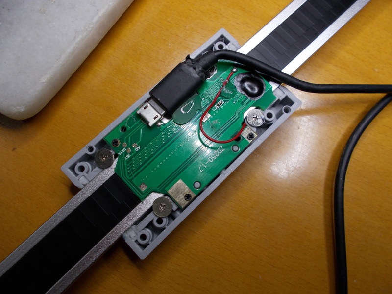
There is a single USB lead between the head and the sensor, the USB lead in plugged into the sensor under the black plastic cover (4 small screws).
It's obviously nothing to do with the USB protocol, simply the designer used USB to connect them together using existing USB hardware.
So the sensor needs no mods and looks exactly as it did before. These are really nice DRO's.(1) Our small workshop layout __ (2) Bandsaw circle cutting jig __ (3) Spindle sander modifications __ (4) Dust Sensor
(5) Router table redesigned ____ (6) DC and where it all began __ (7) Bandsaw dust extraction build
-
19th June 2018, 08:24 PM #125
GOLD MEMBER
- Join Date
- Feb 2016
- Location
- Canberra
- Posts
- 5,125
Its not relevant, entirely, but Im backing this project on Kickstarter: https://www.kickstarter.com/projects...orm-for-makers
It seems like the kind of tool that would be useful to a workshop.
We could chain in a whole lot of sensors (temp, humidity, dust, CO2, fire??, etc), gateways, switches, lights and other things into a single modular package, all controllable and viewable with a smart phone or an internet enabled el-cheapo pad (that can be bashed around wth in the shed).
It's a bit of a crossover with many of BobL's dust projects, but it had me thinking.
I've also been playing with Arduino and this, which is fun: https://www.mysensors.org/
-
19th June 2018, 09:27 PM #126
Woodworking mechanic
- Join Date
- Jan 2014
- Location
- Sydney Upper North Shore
- Posts
- 4,472
21 bit or 24 bit?
-
20th June 2018, 09:05 AM #127
Supporting my wife's hobby.
- Join Date
- Nov 2013
- Location
- Caboolture QLD AU
- Posts
- 781
These are 21 bit, not the more common 24 bit with 2 x 24 bit numbers with relative and absolute positional data. Scale track ground is connected to negative whereas others scale types can be positive. So mixing both typed in one installation requires some precautions with respect to input circuity and isolation.
The clock runs at 9 kHz, and obviously there are 21 clock pulses, 21 bits instead of 24 bits for the absolute position means 3 bits less precision to yield 2560 CPI, really splitting hairs as the precision is impressive and unlike some scales there is no jitter on the data, like I said I haven't had to average the readings, that may change with interference from the spindle motor and stepper circuits. The value returned is the absolute position. Zero, metric, inch and fraction conversions are all done in the head unit. These scales operate as slaves, the master "head unit" supplies the clock signal and power.
I'll post a picture of the scales with the cover off when I get a chance. The Microprocessor I use is 3.3 v Logic (the digital IO's are 5v tolerant though) so the scale wires connect directly to the IO pin header with no other parts needed as the scale are also 3 v logic. Pull-up and Pull-down resistors are programmable in the Micro.(1) Our small workshop layout __ (2) Bandsaw circle cutting jig __ (3) Spindle sander modifications __ (4) Dust Sensor
(5) Router table redesigned ____ (6) DC and where it all began __ (7) Bandsaw dust extraction build
-
20th June 2018, 01:42 PM #128
GOLD MEMBER
- Join Date
- Jun 2005
- Location
- Helensburgh
- Posts
- 7,696
Mike, I will ask this question here so anyone who is following this thread will know the answer.
What motors and drives are we going to use for the fence and height positioning?
For those who are wondering Mike is using these DRO's (150mm) https://www.timbecon.com.au/measurin...t-scales-dro-s
They will be fixed to the guide rails such as these...https://www.ebay.com.au/itm/AU-2PCS-...UAAOSwb3laFkYW These are used for both the fence and the vertical travel sized to suit the table.CHRIS
-
20th June 2018, 06:26 PM #129
Woodworking mechanic
- Join Date
- Jan 2014
- Location
- Sydney Upper North Shore
- Posts
- 4,472
Found this.
Reading Grizzly iGaging DRO Scales with Arduino | Yuriy's Toys
interesting read, as are his other builds
-
20th June 2018, 06:42 PM #130
SENIOR MEMBER
- Join Date
- Dec 2017
- Location
- Aldinga Beach
- Posts
- 478
I still program "Microchip" microcontrollers with a Basic language.....i would however not call it "c...". I also have a C - compiler but i love my basic compiler Originally Posted by MandJ

-
20th June 2018, 07:32 PM #131
Supporting my wife's hobby.
- Join Date
- Nov 2013
- Location
- Caboolture QLD AU
- Posts
- 781
I still program all 8 bit and 16 bit micros in Assembler as I'm fast and at home with it, I'm usually writing time specific code. The Basic built into the 32 bit Explorer 100 is specifically written for this branch of processor and built into the firmware, it encompass dozens of pre coded functions and Procedures to drive many external devices including different sizes of LCD touch screens etc. It includes full floating point maths and can call embedded "roll your own" C functions from Basic. BTW the Basic interrupter in this is completely different to the Basic in the PICAXE series using Microchip devices.
(1) Our small workshop layout __ (2) Bandsaw circle cutting jig __ (3) Spindle sander modifications __ (4) Dust Sensor
(5) Router table redesigned ____ (6) DC and where it all began __ (7) Bandsaw dust extraction build
-
20th June 2018, 07:35 PM #132
Woodworking mechanic
- Join Date
- Jan 2014
- Location
- Sydney Upper North Shore
- Posts
- 4,472
In regards to your post re the 32 bit microchip microprocessors you use, and the kits, where do you purchase them from?
Thanks.
-
20th June 2018, 07:39 PM #133
Supporting my wife's hobby.
- Join Date
- Nov 2013
- Location
- Caboolture QLD AU
- Posts
- 781
Interesting, I wrote my own code and there are some things that I do differently for the same result, the code snippet at least gives someone a start but the sign routine for negative numbers seems strange. The micro I'm using only runs at 120 Mhz so I had to keep any maths out of the clock and data input loop. However I can easily run a number of scales at the same time with this. Originally Posted by Lappa
I'll look more when I get the time.(1) Our small workshop layout __ (2) Bandsaw circle cutting jig __ (3) Spindle sander modifications __ (4) Dust Sensor
(5) Router table redesigned ____ (6) DC and where it all began __ (7) Bandsaw dust extraction build
-
20th June 2018, 07:44 PM #134
Supporting my wife's hobby.
- Join Date
- Nov 2013
- Location
- Caboolture QLD AU
- Posts
- 781
I'll look it up for you, they were available from Silicon Chip, not sure if they still have stock, last I looked the site was confusing with to many options listed, need to know what you actually need in the kit. I know they are available from NZ but that costs more with freight. Originally Posted by Lappa
I've got the articles on the device and building the kit, I could email them to you if you like, just PM me with an email address if you want them.(1) Our small workshop layout __ (2) Bandsaw circle cutting jig __ (3) Spindle sander modifications __ (4) Dust Sensor
(5) Router table redesigned ____ (6) DC and where it all began __ (7) Bandsaw dust extraction build
-
21st June 2018, 03:24 PM #135
Supporting my wife's hobby.
- Join Date
- Nov 2013
- Location
- Caboolture QLD AU
- Posts
- 781
The Anti backlash Ball Screw turned up, this is a really solid little unit, I can not detect the slightest play in this thing, backlash would be zero in a Router table, really, really impressed with this for a Spindle or Router lift. Might need a longer one for the fence though.
Found a strange problem with reading the DRO slide. There is a difference of 2.87 mm between zero and the max travel position of the slide. The Supplied head unit displays 2.87 mm less than my Micro and software.
I'm using an expensive Digital Storage and Real-time Oscilloscope, my Micro generated Clock waveform was better than the head supplied unit, data input is perfect, not a single glitch. The amount is always EXACTLY the same. The start position offset (on power up) of the Slide is exactly the same with my micro and the Head unit.
Tried another head unit as I was wondering if there was some kind of calibration in play - but both supplied head units match exactly. I wasted half a day trying everything until I was convinced that something was being done in the Head units.
So I applied a scale correction factor, - bingo - mine now matched the supplied head unit exactly for any readings from Zero over the entire length of the scale slide.
I have never heard of that, but then again I have not found anything on the Easy-View version of the iGaging DRO, just a passing comment here and there.
EDIT: Looks like this is not uncommon in various scales, and somewhat expected, they use various means to apply a correction in software, so I'm thinking that these scales have a similar production variation, BTW the head units I tried were from different size scales, anyway I will now include a user adjustable scale correction factor in the unit.
Picture of the DRO scale slide with the back off and the USB connection.
 (1) Our small workshop layout __ (2) Bandsaw circle cutting jig __ (3) Spindle sander modifications __ (4) Dust Sensor
(5) Router table redesigned ____ (6) DC and where it all began __ (7) Bandsaw dust extraction build

 Reply With Quote
Similar Threads
-
Router table - Build or buy?
By Dazm in forum ROUTING FORUMReplies: 9Last Post: 12th November 2015, 11:35 AM -
New router table build - no really!
By snowyskiesau in forum ROUTING FORUMReplies: 24Last Post: 14th November 2013, 08:02 AM -
New router table build
By snowyskiesau in forum ROUTING FORUMReplies: 12Last Post: 27th May 2012, 01:35 PM -
Another router table build.
By Nihilist37 in forum ROUTING FORUMReplies: 2Last Post: 31st May 2009, 07:30 PM -
Want to build a table for router and cms
By Guy in forum HAND TOOLS - POWEREDReplies: 3Last Post: 23rd June 2004, 12:31 AM
