

 Thanks: 0
 Likes: 0
 Needs Pictures: 0
 Picture(s) thanks: 0
Results 1 to 15 of 55
-
17th February 2007, 06:32 PM #1
 Novice


- Join Date
- Feb 2007
- Location
- Melbourne, Victoria
- Posts
- 21
 COMPLEX roof - HELP! - Hip end with offset partial octagonal
Howdy all..
I never did an apprenticeship, and I'm about to pitch my first roof. Well, I did a trussed gable end roof for a run of bike sheds in the UK, but that was just like leggo. I feel like I'm going from sandcastles to skyscrapers in one step. I'm not scared exactly, but close. You'll see why. It's taken me ten revisions of the pitching diagram to get to this point, so I understand the shape well - forgive me if I dont convey it well!
This is a stick built coupled roof being done as part of an extension and renovation. There is a bunch of steel work in the new framework, and some complexities added by a very low ceiling height and local planning height restrictions. I've got my head around most of it, but I'm struggling with how to construct the area around the short minor ridge, and the very long shallow broken hip associated with it (running WNW of the octagonal part's peak). I can't get any full common rafters onto the minor ridge at all!
The drawing attached shows the plan view with the proposed hip, valley and ridge locations. It doesn't show internal walls, but the SW corner is BR2 and the octagonal roof is over BR3. The existing roof is to the north and we are extending it to the south, with a hip end, and the octagonal area intersects what would be the south-east corner of the hip end.
The line A-A' shows the approximate line of the original hip end's fascia. The extension south of this point has a 190mm step in the floor, and a corresponding step in the ceiling. However, local planning rules mean that on the west face we can't have either eaves or a higher fascia line. So, the SW corner (BR2) has bulkheads on both walls, 190 high and 400 wide, to hide the structural beams shown in that corner (N-S is steel, E-W is timber). We can have eaves on the other side of the building (further from property boundary) so we have them as shown (400 wide) to avoid having bulkheads in the other bedroom (BR3).
To add a tiny bit more complexity, the extension area is being clad in 75mm polystyrene but the original building is BV, so our top plates step out about 90mm at the change. Thankfully the new rafters are 90x not the old 120x so we can squeeze them in with careful underpurlin placement (span limitation).
Lastly, the space available for windows in BR3 (octagonal area) meant that our steel lintels (NE, E and SE walls) have no timber plates on top, so everything is being mounted on individually welded cleats. Yay.
I think I know how to START the setting out, as follows:
1) find the centre of the octagonal area first (midpoints of the east and south fascias of the octagonal area)
2) find the height of the octagonal area from the known pitch of its northern face (same as existing main roof, 25.5 degrees)
3) find the pitch of the SW face from the height of the peak and the plan distance from the SW fascia
4) find the height of the minor ridge from half of the distance from the S fascia of hip end to the N fascia of octagon, and the known pitch.
5) find plan distance square to SW fascia to point where SW face of octagon reaches height of minor ridge.
6) project this parallel to SW fascia to intersection with minor ridge line. This locates E end of minor ridge/W end of broken hip.
But, step 6 is going to be kinda awkward in mid air to say the least!
7) I think I can do ok with the other broken hip (SE from the main ridge) by simply locating where the SE corner theoretically would be.
That should locate all the relevant geometric lines/pitching points.
As for the construction steps, given the shallow pitch of the long broken hip, it's almost like a ridge. I'm planning to treat it as such, and then the octagonal roof area can be treated a bit like a hip end, with the NNE and SSW hip rafters behaving like common rafters, and the ESE hip rafter behaving like a centre jack rafter (what's the right term again?). The other hip rafters slot in like 'conventional' hip rafters, although at different pitches.
My questions to the more experienced out there are:
1) Am I missing anything in the setting out I've described?
2) What sequence of construction would you recommend? I'm thinking of simply working W to E, but tips like what to temporarily strut, putting in temporary common rafters or whatever would be very useful.
3) I'm not planning to put a central rafter to the peak of the octagonal roof on any of the faces. There is simply no room to move if I do that. Is this a bad idea?
4) I can easily run the rafters square to the fascias, but I'm not enjoying putting in the ceiling joists. Anyone got a good idea there, given that I want them to meet the rafters at the same cleats? Besides, I need tie-in, particularly for the timber SW wall. I've already installed ceiling joists from the W wall of BR2 across to a large strutting/hanging beam that runs N-S in the middle of BR3. They're fixed with joist hangers as the beam is low to stay within chamfer limits at the outside walls.
Any other gotchas that come to mind would be very very useful.
This puppy is DEFINITELY going in my CV.
Cheers,
GrantLast edited by ChipperChip; 17th February 2007 at 06:37 PM. Reason: Added explanation of beams in SW corner
-
17th February 2007 06:32 PM # ADSGoogle Adsense Advertisement
- Join Date
- Always
- Location
- Advertising world
- Posts
- Many
-
17th February 2007, 08:29 PM #2
SENIOR MEMBER
- Join Date
- Apr 2005
- Location
- Queensland, Aus
- Age
- 72
- Posts
- 776

Chipperchip,
This is not a answer to any of the myriad of questions you ask.
In fact I'll be real surprised if:
(a) anyone reads all that you have written,
(b) understands what you want, and
(c) bothers to take the time to write, what I suspect will amount to "Roofing 101", in reply.
Still, maybe someone with the expertise you seek is prepared to take the time.
One thing that does strike me though is, given you are asking a whole bunch of questions, and given you do get a response to them, wouldn't it be a just a bit cheeky to plonk it on your CV as your own work??
Ian
-
17th February 2007, 09:39 PM #3
Senior Member
- Join Date
- Mar 2002
- Location
- Stawell. Victoria
- Age
- 81
- Posts
- 116
Ian,
I'll answer your comments firstly, you are possibly right in your assumption that no one will respond to Chipperchips request. You cannot have a conventional style house layout then suddenly come up with a way out structure like is drawn-up here. Chipperchip,
Firstly you need some elevations, followed by a scaled set out of your intention, what you have there simply is not workable, you have unequal pitches on your rooves, your eaves overhangs will also vary considerably. You made mention of the fact that you did not undertake an apprenticeship, that becomes obvious with your sketch and also your notations for various theories. Not an easy one to solve in its present state, obviously you are doing this as an owner-builder because the building inspector should have pointed things out to you early on. I assume you have not looked at any costings as yet either.
Suggestions at this stage are, talk to someone that is prepaired to look at house plans, not an architect, someone who may do weekend work in top end renovations. I cannot possibly hope to outline where to start from my end.
Good Luck,
Rona.
-
18th February 2007, 12:13 AM #4
GOLD MEMBER
- Join Date
- May 2003
- Location
- Kuranda, paradise, North Qld
- Age
- 62
- Posts
- 5,639
Grant,
that's a total brainf**k . I quite enjoy challenges and helping people on the forums but I've a feeling that Ron is right and thati t's not possible. Do you have proper drawings for this job? If you really mean to go ahead with it I'd suggest telling the client (or yourself if you're going owner builder) to spend the money to get it all drawn up by someone with a 3D CAD program. Get them to do one of those wireframe type drawings that you can view from all angles and see if it is, in fact, possible. It may also show you that it may end up looking like a dog's breakfast.
Mick"If you need a machine today and don't buy it,
tomorrow you will have paid for it and not have it."
- Henry Ford 1938
-
18th February 2007, 12:22 AM #5
Novice
- Join Date
- Feb 2007
- Location
- Melbourne, Victoria
- Posts
- 21
Ok, I'll resist the feeling of being talked down to ;-)
This roof was designed by the architect for this build. I'm the poor sod who's got the job of turning it into a functioning pile of wood and tiles. I've already put this in front of two experienced framing carpenters I know, but unfortunately neither of them have done much coupled roof framing other than repairs and minor mods - their experience has also been almost exclusively in trussed roofs.
First up, Ian, if you suspect a useful reply "will amount to "Roofing 101"" then I suggest you stick to making furniture and using your triton to rip 2mm slices off the bottom of doors. I hope it was a pretty door mate. Buy yourself a planer. I came here looking for help with a genuinely tricky roof, not abuse from a habitually condescending smart alec.
Rona - Firstly sorry to read about your health, you have my very best wishes. Secondly, thanks for your comments. Whilst I haven't done an apprenticeship, I have been working as a construction carpenter for 5 1/2 years both here and in the UK, doing structural work, framing, fixing, floors, stairs and kitchen fits mostly. No roof framing though. If my terminology is off I blame learning my trade in the UK That and being inexperienced with roof framing. For what it's worth I also have a first-year-out qualified chippie from Ireland, a third year apprentice and a second year apprentice on site with me, and I have more experience than any of them with structural work.
The roof layout is a result of the architect extending the octagonal room below straight up, and this is all on the inspected and planning-approved drawings. The roof we removed before extending up was simply an octagonal roof on the end of an E-W minor ridge - considerably simpler and something I've half built in the past from a friend's trade school notes (I simply didnt have time to devote to finishing it).
The ceiling height change isn't on the original approved drawings though, as the architect hadn't done a site visit and had missed the step in the existing lower ceiling that has now resulted in the step upstairs, and the beams and eaves.
Sorry if I've left some stuff out - I was trying to keep clutter on that drawing to a complete minimum. That sketch is actually to scale (CAD output) that I drew up from site measurements - yes, the framing is already up. Attached is a similar sketch showing what the pitches should be. The highest is 27.2 degrees, and the lowest is 25.5. There will be no significant difference in eaves overhangs. I have another showing hip and valley runs. I also have a basic elevation I produced from an earlier proof-of-concept plan, but it would need to be reworked. Do you think it's worth re-doing? Perhaps some sections?
This roof WILL work, and it will go up substantially as shown - I'm just trying to get some idea on how to do it in less than two weeks
Where's Pawnhead?
-
18th February 2007, 01:07 AM #6
Novice
- Join Date
- Feb 2007
- Location
- Melbourne, Victoria
- Posts
- 21
Mick:
Yeah, that's the way I felt about it at about revision 5 of my own drawings. This is rev 10 and I feel a whole lot better about it. The pitches work and I can see the wireframe in my head, but I still wish I had a 3D CAD package to actually build it in.
That said, I know the architect well, and I can get his 3D Autocad as a loaner. I'm keen to draw it up in 3D just for the experience. In a previous career I was an IT Systems Manager for a string of advertising companies, and before that did desktop publishing, so I'm fairly computer literate Sadly, it would take me at least three days to get that drawing right and I dont have that time spare to take away from the job.
-
18th February 2007, 01:26 AM #7
GOLD MEMBER
- Join Date
- May 2003
- Location
- Kuranda, paradise, North Qld
- Age
- 62
- Posts
- 5,639
Grant,
I had another read of your post, and it's still a brainf**k  . Mind you, it's past midnight and I've had long days lately. Sorry, but the most complex roof I've ever hand pitched was an "L" shaped hip and valley roof at 30 deg. with a verandah surrounding it at 12.5deg. It was all exposed though and all the joints had to be tight and spot on visually. I usually resort to drawing joints out full scale (if possible) on a sheet of ply or a smooth concrete floor when I get stuck. I reckon if it were me building it, I'd be spending more time drawing than marking and cutting.
Now there's an idea, when doing some boat fitouts I had the engineer print out some details so that we could wrap the around pipe sections to get them shaped right. Theoretically you could get the angles and length of each rafter (well at least the length to the centrline of its adjoining piece) If you did this it would be a bit like a meccano set.
Mick"If you need a machine today and don't buy it,
tomorrow you will have paid for it and not have it."
- Henry Ford 1938
-
18th February 2007, 01:51 AM #8
SENIOR MEMBER
- Join Date
- Apr 2005
- Location
- Sydney
- Age
- 63
- Posts
- 1,619
I'm here and I'm putting a post together now. It's late though and there's a lot to think about in that one Chipsy. I might not post until the morning. Originally Posted by ChipperChip

You should have no problems if you're capable though.
I'll just ask, are they exposed rafters in the octagon?
edit: - For anyone else, just PM me if you wish to draw my attention to a thread, or ask a question.
-
18th February 2007, 02:42 AM #9
Novice
- Join Date
- Feb 2007
- Location
- Melbourne, Victoria
- Posts
- 21
Mick, it'd be nice to see that exposed rafter work. Challenging but rewarding I'll bet. I had thought of the whole meccano approach but I dont know that I trust my CAD quite THAT much
Maybe one go at cross-checking some dims on my CAD with the real world might get me that confidence. I'll have a look at it Monday because I'm pretty sure the boys wont get that far. (I'm off the tools thanks to a 9" angle grinder taking a liking to my left forearm. I got off lightly thankfully. No major structures damaged, but one big muscle 80% cut. Six weeks off the tools, 2 1/2 to go).
Pawnhead : thanks for looking at this! No, the rafters are not exposed. It's all coupled, with a ceiling, and the eaves will be enclosed too (hangers and eaves joists).
Please, if anyone needs more info I'd be very happy to provide it. Doing so will just make me think about it from another perspective and iron out any kinks I might not have noticed.
Thanks again all.
ps: I should point out that in these sketches the inner perimeter line is the OUTSIDE of the framing, and the outer line is the INSIDE of the fascia. Fairly unimportant since there aren't any dims, but perhaps it will help people visualise things. This is a sketch, people, not a full-on architectural drawing
-
18th February 2007, 04:58 AM #10
SENIOR MEMBER
- Join Date
- Apr 2005
- Location
- Sydney
- Age
- 63
- Posts
- 1,619
Howdy Chipsy Originally Posted by ChipperChip
Neither did I and I taught myself how to pitch a roof with basic trigonometry skills from high school, and by looking at roofs. I like a challenge so Ill have a look at it. It may be a benefit to anyone reading these forums in future as well. Originally Posted by ChipperChip
Is that a scale drawing, because its very wonky. Youll need to start with some accurate ground measurements and you should be able to cut everything on the ground from calculations. Originally Posted by ChipperChip
No problem. Originally Posted by ChipperChip
Understood Originally Posted by ChipperChip
Well you werent joking when you said complex. Originally Posted by ChipperChip
That all sounds reasonable, except youre projecting it in line, not in parallel. Im sure you realise this, but Im just a nit picker. Originally Posted by ChipperChip

Not really. You could pitch it all single handed but it would be a lot quicker with two pairs of hands. Originally Posted by ChipperChip
Its a broken, or flying hip. Its not a ridge. Originally Posted by ChipperChip
I don't know why you'd call them commons. They're bastard hips and they will have to be calculated or measured. Originally Posted by ChipperChip
Theyre all bastard hips according to that wonky drawing. Theyre not the same dimensions as each other either as you realize. Theyre all bastards and it might be easier to measure rather than calculate, after youve got the basic pitches set. Im still thinking about the easiest way to pitch it. Originally Posted by ChipperChip
There are no bedrooms marked, so I dont know what youre talking about. Draw them on the plan. Making a separate ceiling joist plan, would be the best way to convey whats going on. Originally Posted by ChipperChip
Well if you put this together properly, then it would definitely be something to be proud of Grant. Originally Posted by ChipperChip
Thats a bit harsh. These forums are about asking questions of any building matter no matter how complex and time consuming they may be. If you cant offer assistance, then offer encouragement, or say nothing, but dont discourage people from asking questions. Originally Posted by Ian Smith
I happen to have time on my hands, and we all enjoy sharing our knowledge and helping people out. I might get a greenie out of it.As I said, I taught myself how to pitch a roof, but I had help from people dating back to before the first pyramid was pitched. These include Pythagoras, and the people who have pitched the roofs that I have looked at. I didnt invent my methods, and Ill explain them in detail after Ive helped Grant out if you like. Its quite simple if you break it down to one word, and an understanding of basic formula extrapolation. Originally Posted by Ian Smith
If Grant can pitch this roof, and have an understanding of how it was done, so that he can do it again with completely different dimensions, all on his own, then he can proudly say that he built this roof all on his own. He doesnt have to credit his first grade teacher who taught him the basics about simple addition, and he doesnt have to credit me in his CV either.He comes across to me as a person who has a good understanding of a very complex matter, and he's asking the right questions. He has explained everything clearly and I understand everything that hes talking about. Originally Posted by rona
Dont let them worry you Grant. Its just the way the internet works. Originally Posted by ChipperChip
Originally Posted by ChipperChip


-
18th February 2007, 05:03 AM #11
SENIOR MEMBER
- Join Date
- Apr 2005
- Location
- Sydney
- Age
- 63
- Posts
- 1,619
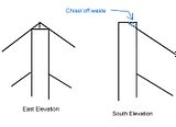
That gives me a better idea of what’s going on (sort of). So it’s an upper floor extension? Are the fascias going to be the same level all the way around? Are you marrying in to an existing fascia? Originally Posted by ChipperChip
Post it all up and I’ll have a look at it. Originally Posted by ChipperChip
Of course it will, and you should have no problems with the manpower you’ve got, depending on how big it is of course. There’s no dimensions that I can read. Originally Posted by ChipperChip
I’m just trying to get the hang of Googles free Sketch Up CAD program. It takes me longer than pencil and paper, but with practice it would be a handy tool. Originally Posted by ChipperChip
That’s how my old man taught me originally. He was a cabinetmaker, turned carpenter after he migrated here. It’s not the easiest way though. You can get that little red roofing book that I’ve heard of, but it doesn’t give you any understanding, and I’m not sure if it covers bastard angles. Ditto for the roofing square method. Originally Posted by journeyman Mick
The most accurate way is through trigonometry. With a $10 calculator and a little bit of knowledge, you can calculate anything that you want, with any combination of dimensions and angles, to an accuracy of however many decimal places that your calculator goes to.Yeh I realised that when you started talking about ceiling joists. I was part way through getting my head around it. Can you provide an accurately dimensioned floor plan, including the offsets of the supporting levels (timber/steel beams) in plan and elevation. I don't mean an elevation drawing, just the height differences will do if they are already set in place, and the offsets measured to the outside corner, either from the inside of the fascia, or the outside of the existing pitching point. Originally Posted by ChipperChip
I know that you've described them, but if you could include dimensions on that plan it would be much more understandable.
Are the fascia boards going to be the same level all the way around?
Is that CAD drawing accurate? Because the South East face of the octagon doesn't run at 45 degrees on that drawing.
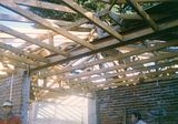
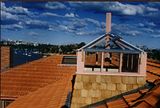
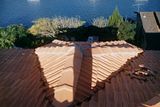
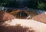
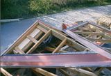
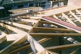
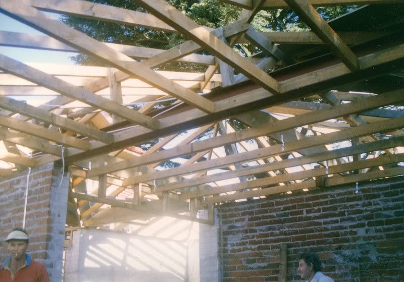
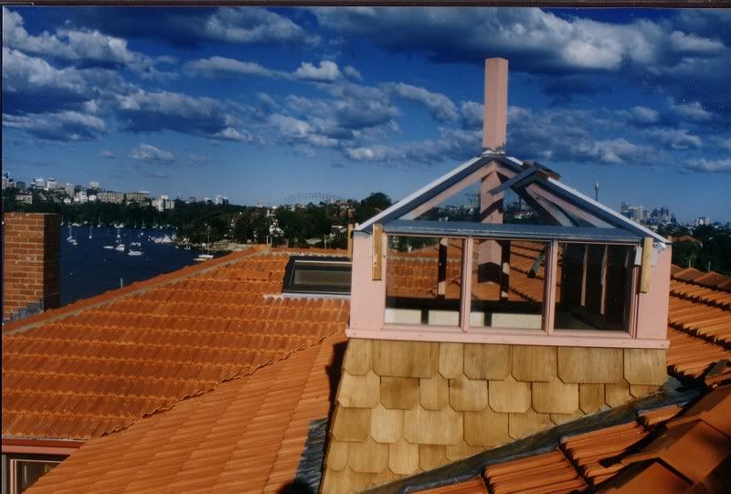
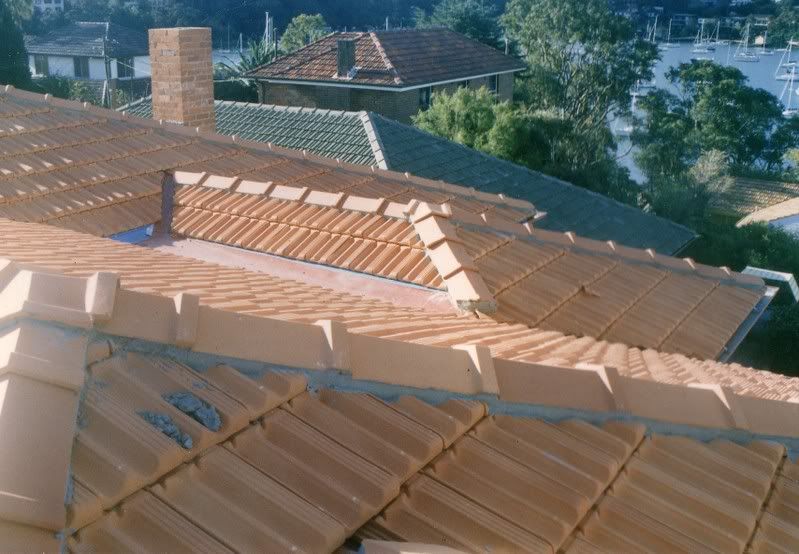
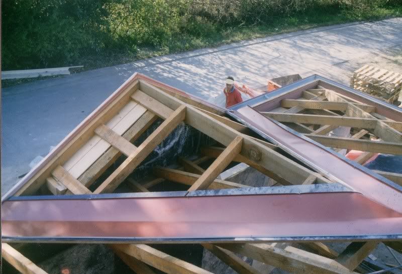
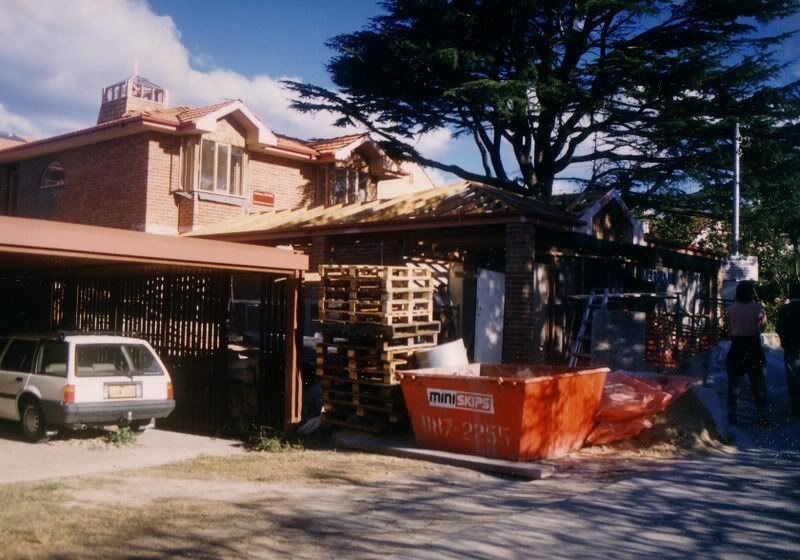
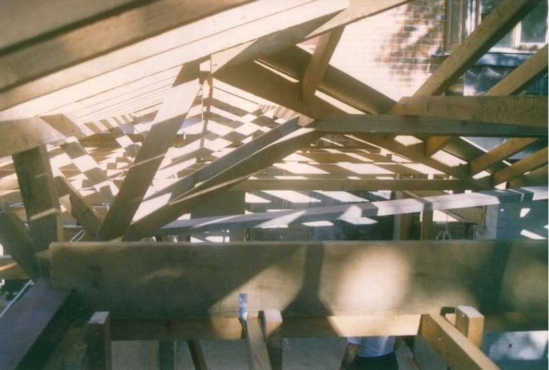
Here’s some pics of a job I did ages ago. I was foreman with four chippies under me, and all I’d pitched before that was a simple gabled roof, but it’s just a compilation of the same methods I used. It was during a long rainy spell so we cut all the rafters inside under the first floor slab, and I was a bit nervous that my calculations would be right. The boys did the straightforward stuff, and I tackled the (part octagon) bay window, and the lighthouse on top. It had exposed rafters and posts, with glazed sidelights and roof and it looked pretty sexy when it was done.


-
18th February 2007, 08:39 AM #12
SENIOR MEMBER
- Join Date
- Apr 2005
- Location
- Sydney
- Age
- 63
- Posts
- 1,619
It’s a long time since I’ve pitched a roof so I’m a bit rusty. I won’t guarantee that I won’t make a mistake somewhere, but mistakes will generally stand out like dogs nuts. You can double check each trig calculation that you make, by attacking it from a different angle and you should come up with the same results.
Firstly, if the fascias are all the same height, then forget about eaves, pitching points, offset heights, etc, for the moment, and concentrate on the height in the centre of the rafter/valley/hip at the top, at the very bottom end, just behind the fascia board.
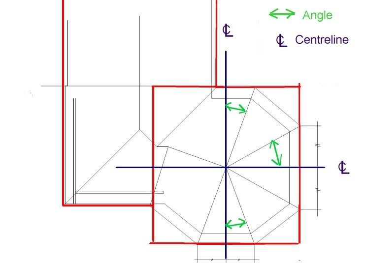
Then don’t think of an octagon, but think of a square, layed on top of a rectangle. Then to get your irregular octagon, work out these three angles: -

Then you can work out the pitch of each with the following formula: -
[tan roof pitch / (1 / cos angle ) ] atan = hip pitch
Then work out the offset from the end of the rafter to the outside of your pitching point, and calculate the height difference using trig (I’m assuming you know how). Allow for the plumb depth of the rafter, less the birsmouth. This depth is the same plumb distance on your hips, but you have to bear in mind that the top corners of the hips must be planed down to a point in the middle, in line with the plane of the roof. You can leave the top square if drop the hip accordingly. It’s just another compound angle to work out. The face of the birdsmouth can also be cut to an internal point, if you want tight joinery. I’d only bother with that if they were exposed.
Your rafters aren’t exposed, but if they were then you’d have to get your hips coming to a point in the centre (or pitch them to an octagonal block at the top).
Your cheek cuts are simply half the angle between hips, taken horizontally. I don’t bother working out the angle on the pitch. I simply lay down my saw on a 45 and cut to the long point with a plumb cut, then set my bevel to an angle, and start planing with the electric planer. Check the angle, square from the plumb cut, not parallel with the rafter, and check it with a straight edge, taking less off as you get closer to home.
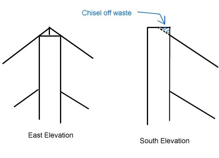
But since you’re rafters aren’t exposed, I’d do it differently, with a method that makes it easier to get it up there, not having to join pointy rafters together. I’d pitch three common rafters over the octagon first as shown here: -
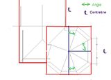
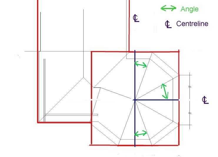
Work out the lengths using trig, and then pitch the two opposing rafters first. The third rafter butts into the side of the first two, so it has to be half their thickness shorter, measured horizontally from the plumb cut. The top corners of the rafters should line up with each other, and it should look like this in elevation: -
Then get up on the ridge with a short straight edge a pencil and a chisel. chisel off the part of the abutting rafters to the centrepoint,then sight the straight edge from the centerpoint to the corner of the octagon (pitching point) and mark the top of the rafters with a hip centreline. Then drive a nail in the outside corner of the rafter at the hip centreline. Hook your tape on it and measure diagonally from this point to the pitching point intersection. Cut and plane the top of your hip rafter to the appropriate angle. In the region of your birdsmouth, mark a plumb line and measure down the depth of rafter remaining above the birdsmouth. From this point mark a parallel line on the rafter. With your tape extended and locked, position it on a diagonal from the top centre, down to the parallel mark at the birdsmouth. Adjust its position until the length coincides with the line and the centrepoint at the top and mark it. You now have the position of your birdsmouth. Cut and install.
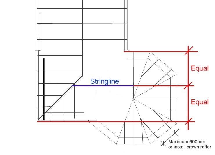
In plan, after your hips are installed it should look like this: -
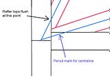
At the top intersection you will find that the top of the hips are lower than the rafters at their long point, and they stick above them on their short point. Using a straight edge, or line of sight between adjacent rafters, plane the tops to a point. All of the roof planes should converge to the centre point now.
Hook your tape on top of your rafter and measure perpendicular towards the hip. Mark 600mm on the top of your hip, then move down the rafter and mark 1200mm, etc. These are the long points for your creeper rafters, and after marking their positions on the pitching plate, you can use the diagonal measuring technique to cut all your creepers. They all step down in the same incremental lengths, and they should be the same lengths for both sides, except with opposite bevels on the top.
Now you have the Eastern half of your octagon pitched.
TBC
-
18th February 2007, 10:10 AM #13
SENIOR MEMBER
- Join Date
- Apr 2005
- Location
- Queensland, Aus
- Age
- 72
- Posts
- 776
Chipperchip,
You're right, I should stay out of things I know nothing about, so I do apologise if I've pushed your buttons.
I still think you might hold the record for the biggest and most complex OP for a thread, but it looks like you've struck paydirt with Pawnhead - so good luck.
Ian
-
18th February 2007, 11:51 AM #14
Novice
- Join Date
- Feb 2007
- Location
- Melbourne, Victoria
- Posts
- 21
Wow, Pawnhead. A string of things come to mind! Many thanks again, and I'm in utter awe of that first roof of yours. I'm good with trig, but in fact I've cheated a bit with my calculations so far and have manged to get away without any trig so far. I've used pythagoras' of course (which is really just basic geometry). I've used ratios taken off the original roof, and dims off my CAD.
I'll do some more drawings and come back later. Is there any easy way to post higher-resolution images than the 800x600?? I'll go digging thru the forums, it's got to be something people have asked before.
Yes, yes and yes. Sorry again for missing stating those up front. My tired brain was forgetting you haven't been thru the same process I have Originally Posted by pawnhead

Yes it is pretty much perfect. And you're right, it's not at 45 degrees. It's about 40 & 50. So this isnt just a regular octagon, it's a slightly squashed one. Dont you love renovations. Actually, architecturally it has to be squashed to make the courtyard below work. Originally Posted by pawnhead
I'll do a much more thorough plan view with the internal walls, remaining propping beams, dims and R.L.'s. I'll try to knock up a section, and a ceiling joist plan sounds like a very good idea. I just need more detail than I can squeeze into a 100k jpg What I'll also try to do is something to demonstrate what I meant by treating those bastard hips as commons...
Once again, huge amounts of thanks to you Pawnhead - I hope you drink beer mate One of my side projects at the moment is building a microbrewery.
-
18th February 2007, 12:07 PM #15
SENIOR MEMBER
- Join Date
- Apr 2005
- Location
- Sydney
- Age
- 63
- Posts
- 1,619
Ah, OK. I'll address your post later and explain trig a bit better if you want, but I've been pretty busy with other matters this morning, and I'll have to go out now so I'll post again tonight some time.
I've got this much ready anyway: -
Next, using trig, pitch as much as you can of the standard hip roof, from the existing roof traveling Southward.
If you’re not familiar with trig I can explain it to you. You obviously need to understand it well for most aspects of my methods, but there’s a handy calculator that you can use for a basic rectangular roof set out. One of the members here. Blocklayer, has the program on line on his website here.
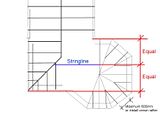
Before you pitch the southernmost rafters, and the creeper rafters, put a temporary prop under the ridge so it’s dead level. Then run a stringline on top of the rafters, as illustrated here: -
Anyone should feel free to ask questions if they are confused and interested, but I’ll deal with Grant first.


Similar Threads
-
I give up - my Triton won't cut straight. Anyone work out what's wrong from this pic
By toddles in forum TRITON / GMCReplies: 24Last Post: 8th August 2006, 01:54 AM
